nuwave pressure cooker manual

NuWave Pressure Cooker Manual: A Comprehensive Guide

This manual provides comprehensive guidance for the NuWave Nutri-Pot Digital Pressure Cooker, covering setup, operation, safety, and maintenance.
It ensures optimal performance and delicious results with your new kitchen appliance!

Explore preset functions, manual adjustments, and cooking times for various foods, including beans and rice.
Understand pressure release methods and the kPa/PSI relationship for safe and efficient cooking.

Discover how to utilize the warm function for convenient meal timing and access recipe inspiration.
This guide empowers you to unlock the full potential of your NuWave pressure cooker.

Understanding Your NuWave Nutri-Pot

The NuWave Nutri-Pot is a versatile electric pressure cooker designed for convenient and efficient cooking. It operates at a pre-programmed pressure of 70kPa, a standard measurement widely used globally instead of PSI (Pounds per Square Inch). Understanding this kPa setting is crucial for consistent results. Approximately, 2 PSI equates to 14kPa.

This appliance simplifies meal preparation by significantly reducing cooking times compared to traditional methods. Its digital control panel allows for precise adjustments to both time and pressure, offering flexibility for various recipes. The Nutri-Pot isn’t just for pressure cooking; it also features a ‘Warm’ function, capable of keeping food at a safe temperature for up to four hours, ideal for delayed meal service.

Key to its functionality is the ability to prepare food in advance and maintain its quality using the warm setting. However, prolonged warming beyond four hours may affect flavor, texture, and potentially lead to spoilage. The Nutri-Pot is available in various models, like the BM33100 6qt, each designed to deliver consistent performance.

Model Numbers and Variations

NuWave Nutri-Pot pressure cookers are available in several models, catering to diverse cooking needs and preferences. A commonly referenced model is the BM33100 6-quart version, a popular choice for families. Another variant is the 33101 Quart Digital Pressure Cooker, offering similar functionality with a slightly different capacity.

While core features remain consistent across models – like the 70kPa operating pressure and preset functions – subtle variations may exist in control panel layouts or included accessories. It’s essential to refer to the specific owner’s manual accompanying your model for accurate details.

Regardless of the model, all NuWave Nutri-Pots share the same commitment to simplifying pressure cooking. Accessing the complete owner’s manual and recipe book, often available for download on ManualsLib, is highly recommended. These resources provide detailed instructions and culinary inspiration tailored to your specific NuWave appliance, ensuring optimal performance and safety.

Key Components of the Pressure Cooker

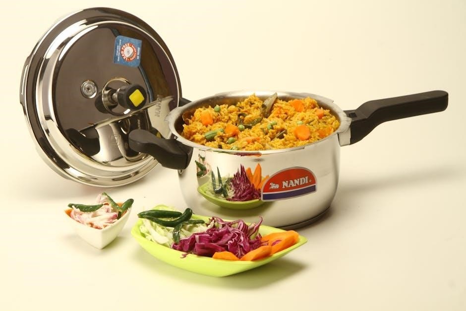
The NuWave Nutri-Pot comprises several essential components working in harmony. The inner cooking pot, typically made of durable materials, holds the food during the cooking process. A crucial element is the silicone gasket, ensuring a tight seal to build and maintain pressure safely.

The control panel, featuring buttons for preset functions, time adjustment, and start/stop, allows for intuitive operation. A pressure release valve regulates internal pressure, offering options for natural or quick release. The exterior housing provides insulation and structural support.

Understanding each component’s function is vital for safe and effective use. Proper gasket installation is paramount for achieving the correct pressure. Regularly inspecting these parts ensures longevity and optimal performance, as detailed in the comprehensive owner’s manual. Familiarity with these elements unlocks the full potential of your NuWave pressure cooker.

Getting Started

Before first use, carefully inspect the NuWave Nutri-Pot and its components. Ensure all parts are present and undamaged, preparing for safe and efficient pressure cooking!

Initial Setup and Inspection

Upon unboxing your NuWave Nutri-Pot, thoroughly inspect all components for any shipping damage. Verify the presence of the pressure cooker base, inner pot, sealing ring (silicone gasket), steam release valve, and any included accessories. Carefully examine the inner pot for dents or warping, and ensure the sealing ring is clean and pliable – a proper seal is crucial for safe operation.

Before the first use, wash the inner pot, sealing ring, and steam release valve with warm, soapy water. Rinse thoroughly and dry completely. Inspect the pressure cooker base, paying close attention to the heating element and control panel. Ensure there are no visible defects. Confirm the steam release valve moves freely and seals correctly. Proper inspection guarantees a safe and enjoyable cooking experience with your new NuWave Nutri-Pot!

Familiarize yourself with the cooker’s features and read the entire manual before proceeding. This initial setup is vital for optimal performance and longevity.

Silicone Gasket Installation

Proper installation of the silicone gasket is paramount for achieving a secure seal and safe pressure cooking with your NuWave Nutri-Pot. Locate the groove within the lid of the pressure cooker – this is where the gasket will sit. Ensure the groove is clean and free of any debris before proceeding.

Carefully stretch the silicone gasket and position it evenly within the groove, working your way around the entire circumference of the lid. The gasket should fit snugly but not be overly stretched or distorted. Verify that the gasket sits flush against the lid, with no gaps or unevenness. A compromised seal can lead to pressure leaks and unsafe cooking conditions.

Regularly inspect the gasket for cracks, tears, or hardening. Replace the gasket if any damage is detected. A well-maintained gasket is essential for consistent and safe operation of your NuWave pressure cooker.

Understanding the Control Panel

The NuWave Nutri-Pot’s control panel is designed for intuitive operation. The Start/Stop button initiates and terminates cooking cycles. Time buttons allow for manual adjustment of cooking duration, displayed in minutes and hours. The Preset Function buttons (Rice, for example) offer pre-programmed settings for common dishes.

Observe the display; during preheating, it will show “PH,” indicating the unit is reaching the appropriate temperature. Once pressure is reached, the cooking timer will begin counting down. The Manual bar illuminates when custom time and pressure settings are selected.

Familiarize yourself with the pressure unit display, understanding the difference between kPa and PSI. The control panel provides precise control over your cooking process, ensuring consistent and delicious results.

Operating Instructions

Begin by ensuring the silicone gasket is correctly installed. Select your desired preset or manually adjust time and pressure.
The NuWave Nutri-Pot will automatically regulate pressure during the cooking process!

Pressure Cooking Basics

Pressure cooking with the NuWave Nutri-Pot utilizes a sealed environment to increase boiling point, significantly reducing cooking times. The cooker is pre-programmed to a set pressure of 70kPa, a globally recognized unit equivalent to approximately 2 PSI. This method retains more nutrients and flavors compared to conventional cooking.

To begin, ensure sufficient liquid is added to create steam – this is crucial for proper pressure build-up. Secure the lid, ensuring a tight seal. The cooker will then enter a preheating phase, indicated by “PH” on the display, as it reaches the desired temperature and pressure. Once pressure is reached, the timer will begin counting down.

Remember that pressure cooking isn’t simply about reducing time; it alters food textures. Foods become tender and flavorful due to the intensified heat and moisture. Always refer to recommended cooking times for specific ingredients, adjusting as needed based on personal preference. Understanding these basics will unlock the full potential of your NuWave Nutri-Pot!

Using Preset Functions (Rice, etc.)

The NuWave Nutri-Pot features convenient preset functions designed for common dishes like rice, simplifying the cooking process. These presets automatically adjust cooking time and pressure for optimal results. For rice, options include Default, Less, Normal, and More, allowing customization based on rice type and desired texture – cooking times range from 7 to 13 minutes.

To utilize a preset, simply select the corresponding button on the control panel. The cooker will then initiate the preheating phase (“PH” indicator) before commencing the timed cooking cycle. Upon completion, the unit will beep, signaling the end of the cooking process.

Notably, the rice preset maintains a warming function indefinitely after completion, keeping your rice at the perfect serving temperature until the Start/Stop button is pressed. This feature, and others like it, make meal preparation and timing incredibly convenient.

Manual Time and Pressure Adjustment

For customized cooking, the NuWave Nutri-Pot allows manual adjustment of both time and pressure. To enter manual mode, press the “Time” button; the “manual” bar will illuminate, and “00:01” will flash on the display. Use the “+” and “-” buttons to set your desired cooking time in minutes and hours.

The NuWave Nutri-Pot is pre-programmed to a set pressure of 70kPa, a widely used unit of pressure measurement globally, instead of PSI. Remember that 2 PSI is approximately equal to 14 kPa. While the pressure isn’t directly adjustable by the user, understanding this unit is crucial for recipe conversion.

This flexibility empowers you to cook a wider variety of dishes according to specific recipes or personal preferences. Always ensure the lid is securely locked before initiating a manual cooking cycle for safe operation.

Preheating Phase (PH Indicator)

During operation, the NuWave Nutri-Pot undergoes a preheating phase before pressure cooking begins. This crucial step ensures the cooker reaches the appropriate temperature for the selected function, guaranteeing optimal cooking results and food safety.

While the unit is preheating, the display will clearly show “PH,” indicating that it is building pressure and temperature. Do not attempt to open the lid during this phase, as it is pressurized and could cause injury. The preheating time varies depending on the amount of food and liquid inside.

Once the “PH” indicator disappears, the cooking cycle officially commences. This visual cue confirms the cooker has reached the desired pressure and temperature, allowing for consistent and reliable performance. Patience during preheating is key to successful pressure cooking!

Cooking Times and Guidelines

This section details recommended cooking times for various foods, including dry and soaked beans, and rice with different texture preferences (Default, Less, Normal, More).

Cooking Dry Beans

Preparing dry beans in your NuWave Nutri-Pot is efficient and yields perfectly cooked results. Rinse the beans thoroughly before cooking to remove any debris. For unsoaked dry beans, cooking times generally range from 20 to 30 minutes, depending on the bean type and desired tenderness. Larger beans, like kidney beans, may require the longer end of the spectrum – around 25-30 minutes.

Smaller beans, such as black beans or lentils, typically cook in approximately 20-25 minutes. Remember that these times are guidelines; always check for desired texture after the initial cooking period. If the beans are still firm, add a few more minutes of cooking time. Conversely, if they are too soft, reduce the cooking time slightly in future attempts.

For optimal results, use the manual pressure setting and adjust the cooking time accordingly. The NuWave Nutri-Pot will beep when the cooking cycle is complete, signaling that the beans are ready. Allow for natural pressure release for approximately 10-15 minutes before manually releasing any remaining pressure.

Cooking Soaked Beans

Utilizing pre-soaked beans significantly reduces cooking time within your NuWave Nutri-Pot. Soaking beans overnight, or for at least 8 hours, rehydrates them, diminishing cooking duration and improving digestibility. When cooking soaked beans, a timeframe of 5 to 10 minutes is generally sufficient, contingent upon the bean variety and preferred consistency.

Smaller bean types, like navy or pinto beans, may require only 5-7 minutes of pressure cooking after soaking. Larger varieties, such as kidney or cannellini beans, benefit from approximately 8-10 minutes. Remember to drain and rinse the soaked beans thoroughly before adding them to the pressure cooker.

Employ the manual pressure setting for precise control over cooking time. After the cycle concludes, allow for a natural pressure release of 10-15 minutes, followed by a careful manual release of any residual pressure. This method ensures tender, perfectly cooked beans every time.

Rice Cooking Times (Default, Less, Normal, More)

The NuWave Nutri-Pot offers versatile rice cooking options through its preset function and adjustable time settings. The default rice cooking time is 10 minutes, ideal for most white rice varieties. However, tailoring the time to your preference and rice type yields optimal results.

For a softer texture, or smaller rice grain varieties, select the “Less” setting, which cooks for 7 minutes. “Normal” (10 minutes) is suitable for medium-grain white rice. If you prefer firmer rice, or are cooking brown rice, choose “More” at 13 minutes. Experimentation is key to finding your perfect rice consistency.

Remember that the cooker will automatically switch to the “Warm” function post-cooking. This keeps the rice at serving temperature indefinitely until the Start/Stop button is pressed. Always allow a natural pressure release for fluffier rice.

Safety Features and Precautions

Prioritize safety by understanding pressure release methods and kPa/PSI values. Never exceed the maximum 4-hour warm function duration to prevent spoilage and ensure safe operation.

Pressure Release Methods

The NuWave Nutri-Pot features multiple pressure release methods for user convenience and safety. Understanding these is crucial for preventing accidents and achieving optimal cooking results. The primary methods are Natural Pressure Release (NPR) and Quick Pressure Release (QPR).

Natural Pressure Release allows the pressure to dissipate gradually over time, typically 10-30 minutes, depending on the food’s volume and temperature. This method is ideal for soups, stews, and foods with high liquid content, preventing splattering. Simply allow the cooker to cool down naturally after the cooking cycle completes.

Quick Pressure Release involves carefully venting the steam through the pressure release valve. Exercise extreme caution as the escaping steam is very hot. This method is suitable for foods where overcooking is a concern, like vegetables. Ensure your hands and face are clear of the steam vent before releasing the pressure. Always follow the manufacturer’s instructions for safe QPR operation.

Failure to properly release pressure can result in food splatter or potential injury. Always refer to the recipe guidelines for the recommended pressure release method.

Understanding kPa vs. PSI

The NuWave Nutri-Pot utilizes kilopascals (kPa) as its standard unit for measuring pressure, a common practice globally, differing from the Pounds per Square Inch (PSI) often used in North America. It’s essential to understand this distinction for accurate cooking and recipe conversions.

kPa is a metric unit of pressure, while PSI is an imperial unit. The NuWave cooker is programmed to a set pressure of 70kPa. To convert between the two, remember the approximate ratio: 2 PSI is roughly equivalent to 14 kPa. Therefore, 70 kPa translates to approximately 10 PSI.

While recipes may list pressure in PSI, you can easily convert it to kPa for use with your NuWave Nutri-Pot. Conversely, if a recipe specifies kPa, you can convert it to PSI if needed. Accurate conversion ensures consistent cooking results and food safety. Familiarizing yourself with this conversion will enhance your pressure cooking experience.

Always refer to the NuWave manual for specific pressure settings and conversion guidance.

Maximum Cooking Time (Warm Function ⎯ 4 Hours)

The NuWave Nutri-Pot features a convenient warm function, designed to maintain food temperature after the pressure cooking cycle is complete. This allows for meal timing flexibility, keeping your dishes ready to serve when you are.

However, it’s crucial to understand the limitations of this function. While the warm function can keep food at a safe temperature for up to 4 hours, exceeding this timeframe is not recommended. Prolonged warming may lead to undesirable changes in flavor, texture, and appearance.

More importantly, extended warm holding can create an environment conducive to bacterial growth, potentially causing food spoilage and posing a health risk. Always adhere to the 4-hour maximum to ensure food safety and quality. Pressing the start/stop button will deactivate the warm function.

For optimal results, consume food within the 4-hour window or transfer it to a refrigerator for longer storage.

Maintenance and Care

Regular cleaning and proper storage are vital for extending the life of your NuWave Nutri-Pot.
Follow the detailed instructions to ensure optimal performance and longevity!

Troubleshooting common issues is also addressed, providing solutions for a seamless cooking experience.
Maintain your cooker for years of delicious meals!

Cleaning Instructions

After each use, ensure the NuWave Nutri-Pot is completely cooled down before cleaning. The inner pot is dishwasher safe, offering convenient cleanup. However, hand washing is also recommended to preserve its finish. The lid, including the silicone gasket, should be washed with warm, soapy water. Pay close attention to the gasket, ensuring it’s free of cracks or damage, as this impacts pressure sealing.

The exterior of the pressure cooker can be wiped down with a damp cloth. Avoid using abrasive cleaners, as they may scratch the surface. For stubborn food residue, soak the inner pot with warm water and dish soap before scrubbing gently. Never immerse the main unit (containing the electrical components) in water or any other liquid. Ensure all parts are thoroughly dried before reassembling and storing. Regular cleaning prevents buildup and maintains optimal performance.

Inspect the steam release valve regularly and clean it to prevent clogging. A clogged valve can affect pressure regulation. Proper cleaning ensures safe and efficient operation of your NuWave Nutri-Pot.

Storage Guidelines

When storing your NuWave Nutri-Pot, ensure all components are completely dry to prevent mold or mildew growth. The inner pot, lid, and accessories can be neatly stacked inside the main unit for compact storage. Store the pressure cooker in a cool, dry place, away from direct sunlight and extreme temperatures. Avoid storing it in a damp basement or a hot attic.

Keep the silicone gasket separate from other items to prevent it from becoming deformed or damaged. It’s recommended to store the gasket in a clean, airtight container. Ensure the steam release valve is also stored separately, allowing for proper ventilation. Avoid placing heavy objects on top of the pressure cooker during storage, as this could cause damage to the unit or its components.

Proper storage extends the lifespan of your NuWave Nutri-Pot and ensures it’s ready for use whenever you need it. Regularly inspect the unit before storage to address any potential issues.

Troubleshooting Common Issues

If the NuWave Nutri-Pot doesn’t pressurize, ensure the lid is securely locked and the silicone gasket is properly installed. Check the steam release valve is in the sealing position. If the unit displays an error code, consult the full owner’s manual for specific troubleshooting steps. Food burning? Reduce cooking time or add more liquid.

A “PH” error indicates the unit hasn’t reached pressure; allow more preheating time. If steam leaks from the lid during cooking, ensure the lid is correctly aligned and the gasket is seated properly. For unresponsive buttons, try unplugging and replugging the unit. If the warm function isn’t maintaining temperature, verify it’s activated correctly.

Remember to always unplug the cooker before attempting any troubleshooting. If issues persist, refer to the complete manual or contact NuWave customer support for assistance.

Recipes and Inspiration

Unlock a world of culinary possibilities with the NuWave Nutri-Pot! A complete recipe book is available, offering diverse dishes. Utilize the warm function to perfectly time your meals.

Recipe Book Availability

Expanding your culinary horizons with the NuWave Nutri-Pot is effortless! A complete recipe book accompanies your digital pressure cooker, brimming with a diverse collection of dishes designed to showcase its versatility. This resource provides step-by-step instructions, ingredient lists, and helpful tips to guide you through each recipe, ensuring successful and flavorful results every time.

Beyond the included book, numerous online resources and communities dedicated to NuWave cooking offer a wealth of additional recipes and inspiration. Websites, forums, and social media groups are filled with passionate cooks sharing their creations and innovative techniques. Explore these platforms to discover new flavors, adapt recipes to your preferences, and connect with fellow NuWave enthusiasts.

Don’t hesitate to experiment and create your own signature dishes! The NuWave Nutri-Pot’s precise controls and multiple functions empower you to explore your culinary creativity and unlock a world of delicious possibilities. Remember to share your successes and inspire others within the vibrant NuWave cooking community.

Utilizing the Warm Function for Meal Timing

The NuWave Nutri-Pot’s warm function is a game-changer for busy schedules, allowing you to perfectly time your meals. Once the cooking cycle is complete, the unit automatically switches to the warm setting, maintaining food at a safe and palatable temperature. This feature is especially useful for delaying serving time without compromising quality or flavor.

However, it’s crucial to remember that the warm function is designed for short-term holding – up to 4 hours. Prolonged warming may lead to changes in texture, appearance, and potentially, food spoilage. Plan accordingly to ensure your meal is enjoyed at its peak freshness. The unit will keep rice warm indefinitely until the start/stop button is pressed.

Take advantage of this feature to prepare meals in advance, freeing up your time for other activities. Enjoy the convenience of a hot, delicious meal whenever you’re ready, thanks to the NuWave Nutri-Pot’s thoughtful design and versatile functionality.

manual remote starter

Remote starters offer convenience‚ especially in extreme weather‚ but professional installation is often recommended due to complex vehicle electronics.

However‚ skilled individuals can save money by performing the installation themselves‚ following detailed guides and understanding vehicle systems.

This article provides a foundational understanding of remote starter installation‚ emphasizing safety and proper procedures for a successful outcome.

What is a Manual Remote Starter?

A manual remote starter is an aftermarket device allowing a vehicle to be started remotely‚ without the physical key being in the ignition. Unlike factory-installed systems‚ manual starters typically require professional or experienced DIY installation‚ involving wiring into the vehicle’s existing electrical system.

These systems bypass the standard ignition sequence‚ engaging the starter motor via a remote control signal. They are particularly useful for pre-heating or pre-cooling a vehicle’s cabin‚ enhancing comfort. Proper installation is crucial‚ as incorrect wiring can potentially damage sensitive vehicle electronics‚ highlighting the need for careful adherence to installation guides.

Benefits of Installing a Remote Starter

Installing a remote starter provides significant convenience‚ particularly in harsh climates. Pre-warming a vehicle in winter ensures a comfortable cabin temperature‚ while pre-cooling in summer offers immediate relief from the heat. This reduces the need to endure extreme temperatures during the initial moments of a commute.

Beyond comfort‚ remote starters can save time by allowing the vehicle to be prepared before occupants enter. While professional installation can be costly‚ DIY installation offers savings for those with the necessary skills and knowledge‚ enhancing vehicle usability and overall driving experience.

Safety Precautions Before Installation

Prioritize safety when installing a remote starter. Disconnect the vehicle’s battery to prevent electrical shorts and damage to sensitive electronics. Thoroughly review the vehicle’s wiring diagrams and the remote starter’s installation manual before beginning. Improper wiring can lead to system malfunctions or even vehicle damage.

Ensure the work area is well-lit and free of obstructions. Use appropriate tools and follow all manufacturer’s instructions carefully. If unsure about any step‚ consult a qualified technician to avoid potential hazards and ensure a safe‚ functional installation.

Understanding Vehicle Compatibility

Ensuring compatibility is crucial; check your vehicle’s electrical system and identify key ignition circuits before installation for a seamless integration.

Checking Your Vehicle’s Electrical System

Before beginning‚ a thorough inspection of your vehicle’s electrical system is paramount. Verify the battery’s health‚ ensuring it provides sufficient voltage for both starting and remote operation.

Inspect all relevant fuses and relays‚ noting their amperage ratings and locations. A multimeter is essential for testing voltage at key points‚ confirming proper circuit functionality.

Pay close attention to the starter‚ ignition‚ and accessory circuits‚ as these will be directly interfaced with the remote starter system. Documenting existing wiring configurations will prove invaluable during installation and troubleshooting.

Understanding the vehicle’s CAN-bus system‚ if equipped‚ is also critical for avoiding interference and ensuring proper operation.

Identifying Key Ignition and Starter Circuits

Accurate identification of ignition and starter circuits is crucial for a successful installation. Utilize a vehicle-specific wiring diagram to pinpoint the wires responsible for each function.

The ignition wire provides power to the vehicle’s ignition system‚ while the starter wire activates the starter motor. Accessory wires power features like the radio and climate control.

Carefully trace these wires from their source to their connection points‚ noting their color coding and gauge. A test light or multimeter can confirm wire functionality during key-cycle testing.

Properly identifying these circuits prevents damage and ensures reliable remote starting.

Compatibility with Automatic vs. Manual Transmissions

Remote starter compatibility differs significantly between automatic and manual transmissions. Automatic transmissions generally require simpler installations‚ often needing only ignition and starter circuit connections.

Manual transmission vehicles demand additional safety measures to prevent unintended vehicle movement. A crucial component is the “hood pin switch‚” which disables the starter if the hood is open.

Furthermore‚ manual transmission systems often require a brake pedal switch connection‚ ensuring the clutch is disengaged before starting. Proper configuration is vital for safe operation and preventing damage.

Always verify compatibility before purchasing a system.

Tools and Materials Required

Essential tools include wiring tools‚ a multimeter‚ and vehicle-specific parts like bypass modules. A complete remote starter system is also necessary for installation.

Essential Wiring Tools

For a successful remote starter installation‚ having the right wiring tools is paramount. A high-quality wire stripper and crimper are essential for creating secure and reliable connections. You’ll also need various gauge wires‚ heat shrink tubing‚ and a heat gun to insulate connections properly‚ preventing shorts and corrosion.

A multimeter is crucial for testing voltage and continuity‚ ensuring correct wiring. Don’t forget electrical tape‚ zip ties for cable management‚ and potentially a soldering iron for more permanent connections. Precision screwdrivers and panel removal tools will aid in accessing vehicle wiring harnesses safely.

Necessary Vehicle-Specific Parts

Beyond the core remote starter kit‚ several vehicle-specific parts are often required. A bypass module is crucial‚ allowing the starter to function without the key present‚ tailored to your car’s security system. You may need a hood pin switch‚ ensuring the vehicle isn’t started with the hood open.

Specific wiring harnesses or adapter cables simplify connections to your vehicle’s existing electrical system. Check compatibility charts to confirm the correct parts for your make and model‚ avoiding generic components that may cause issues.

Remote Starter System Components

A typical remote starter system includes the control module‚ the brain of the operation‚ managing all functions. The remote control‚ usually a key fob‚ transmits the start signal. A wiring harness connects the system to the vehicle’s electrical network.

An antenna receives the remote signal‚ and a hood pin switch adds a safety layer. Some systems include a bypass module‚ crucial for modern vehicles with immobilizers. Ensure all components are compatible with your vehicle’s specifications for optimal performance and reliability.

Installation Process: Step-by-Step Guide

Begin by disconnecting the vehicle’s battery for safety‚ then carefully bypass the ignition switch and connect the starter relay as instructed.

Proper wiring is crucial for a functional and safe remote start system.

Bypassing the Ignition Switch

Bypassing the ignition switch is a critical step‚ allowing the remote starter to activate essential vehicle systems without the physical key present. This process involves identifying the ignition‚ accessory‚ and starter wires‚ typically requiring a wiring diagram specific to your vehicle model.

Carefully connect the remote starter’s corresponding wires to these circuits‚ ensuring secure and insulated connections.

The remote starter must be able to start the vehicle with the key in the ignition barrel‚ but not necessarily turned. Incorrect wiring can damage the vehicle’s electrical system‚ so double-check all connections before proceeding.

Always prioritize safety and consult a professional if unsure.

Connecting the Starter Relay

The starter relay is a crucial component‚ handling the high current required to engage the vehicle’s starter motor. The remote starter system doesn’t directly power the starter; instead‚ it triggers this relay.

Locate the existing starter relay in your vehicle’s fuse box and identify its control wire. Connect the remote starter’s designated starter output wire to this control wire.

Ensure proper grounding and secure connections. This setup allows the remote starter to safely activate the starter motor without overloading the system‚ protecting vital components from damage.

Wiring the Hood Pin Switch

The hood pin switch is a vital safety feature‚ preventing the vehicle from starting remotely with the hood open. This protects both the vehicle and anyone nearby. Locate the hood pin switch – typically a normally closed switch – and identify its wiring.

Connect the remote starter’s designated hood pin input wire to one side of the switch. The other side should be grounded when the hood is closed.

This ensures the remote start is disabled if the hood is raised‚ adding a critical layer of safety during operation.

Integrating with the Vehicle’s Security System

Proper integration with the vehicle’s existing security system is crucial to avoid conflicts and ensure reliable operation. Many remote starters require bypassing or disabling certain security features during remote start.

This often involves connecting to the vehicle’s alarm disarm circuit or utilizing a relay to temporarily disable the security system upon remote activation.

Carefully consult your vehicle’s security system manual and the remote starter’s instructions for specific wiring diagrams and procedures to prevent false alarms or system malfunctions.

Programming and Configuration

Remote control pairing‚ setting appropriate run-time limits‚ and thoroughly testing system functionality are essential steps post-installation for optimal performance and safety.

Remote Control Pairing

Pairing the remote control to the remote starter system is a crucial initial configuration step. Typically‚ this involves a specific sequence of actions‚ often utilizing the vehicle’s ignition switch. Consult the manufacturer’s guide for your specific system‚ as procedures vary significantly.

Common methods include turning the ignition to the accessory position‚ pressing a designated button on the remote‚ and observing indicator lights on the system’s control module. Successful pairing is usually confirmed by a visual or audible signal. Ensure no other remote controls interfere during the process‚ and repeat if necessary.

Proper pairing establishes secure communication‚ enabling reliable remote start functionality.

Setting Run Time Limits

Establishing run time limits is a vital safety and security feature of your remote starter system. Most systems allow you to program the maximum duration the vehicle will run remotely‚ typically ranging from 15 to 30 minutes. This prevents excessive fuel consumption and potential battery drain.

Configuration usually involves a sequence of turning the ignition on and off‚ combined with button presses on the remote control or the system’s module. Refer to your system’s manual for the precise procedure. Consider local regulations and personal preferences when setting the run time.

Adjusting these limits ensures responsible operation.

Testing the System Functionality

Thorough testing is crucial after installing and programming your manual remote starter. Begin by verifying the remote control’s range and responsiveness in various locations around your vehicle. Ensure the starter engages smoothly and the engine runs consistently without stalling.

Test all features‚ including the hood pin switch and security system integration. Confirm the vehicle shuts off as expected when the remote’s range is exceeded or the brake pedal is pressed. Document any issues encountered during testing for troubleshooting.

A comprehensive test guarantees reliable operation.

Troubleshooting Common Issues

Common problems include a failing starter‚ unresponsive remotes‚ or unexpected shutdowns. Careful diagnosis‚ checking wiring‚ and verifying programming are essential for resolution.

Starter Not Engaging

If the starter doesn’t engage‚ first verify the remote’s battery and signal strength. Next‚ meticulously check all wiring connections related to the starter circuit‚ ensuring they are secure and free from corrosion. Confirm the hood pin switch is functioning correctly‚ as it’s a crucial safety feature preventing remote start with an open hood.

Inspect the starter relay; a faulty relay can prevent power from reaching the starter motor. Also‚ double-check the bypass module’s connection to the ignition switch‚ ensuring it’s correctly simulating key presence. A diagnostic scan can reveal any underlying vehicle system errors hindering the remote start function.

Remote Control Not Responding

When the remote control fails to respond‚ begin by replacing the battery with a fresh one. Ensure there’s no radio frequency interference nearby‚ as this can disrupt the signal. Verify the remote is properly paired with the remote starter system; re-pairing may be necessary after a battery change or system reset.

Check the antenna connection at the remote starter module‚ ensuring it’s securely attached. Inspect the vehicle’s security system; some systems can disable remote start functionality. A diagnostic tool can help identify communication errors between the remote and the module.

Vehicle Shutting Off Unexpectedly

If your vehicle shuts off unexpectedly after remote starting‚ a common cause is a faulty hood pin switch‚ incorrectly installed or malfunctioning. This safety feature prevents operation when the hood is open. Verify the switch is properly adjusted and functioning correctly; a loose connection can also trigger this issue.

Inspect the tachometer signal wire connection to the remote starter module‚ ensuring it’s secure. A weak or intermittent signal can cause the system to incorrectly detect engine status. Check for any conflicting aftermarket accessories that might interfere with the system’s operation.

Maintenance and Care

Regular battery checks and secure wiring connections are crucial for optimal remote starter performance. Firmware updates‚ when available‚ enhance system functionality and reliability.

Battery Maintenance for Optimal Performance

Maintaining a healthy vehicle battery is paramount for reliable remote starter operation. Remote start systems draw significant power‚ and a weak battery may struggle to engage the starter‚ leading to frustrating failures. Regularly test your battery’s voltage and charging system to ensure it meets the manufacturer’s specifications.

Consider a battery tender during periods of infrequent use‚ especially in cold weather‚ to prevent excessive discharge. Corrosion on battery terminals can impede current flow; clean them periodically with a baking soda and water solution. A well-maintained battery ensures consistent and dependable remote starting‚ extending the system’s lifespan.

Checking Wiring Connections

Regularly inspect all wiring connections associated with your remote starter system. Loose or corroded connections can cause intermittent operation or complete system failure. Pay close attention to crimped connections‚ ensuring they are secure and properly insulated. Gently tug on each wire to verify its stability within the connector.

Look for signs of fraying‚ damage‚ or exposed wiring‚ and address any issues immediately. Use dielectric grease on connections to prevent corrosion and maintain optimal conductivity. A thorough inspection of wiring ensures a reliable and safe remote start experience‚ preventing unexpected issues.

Updating Firmware (If Applicable)

Modern remote starter systems often receive firmware updates to improve performance‚ add features‚ or address security vulnerabilities. Before updating‚ download the latest firmware and installation guide from the manufacturer’s support website. Carefully follow the provided instructions‚ as incorrect updates can render the system inoperable.

Typically‚ updates are performed via a USB connection to the remote starter’s control module. Ensure a stable power supply during the update process to prevent data corruption. Regularly checking for updates keeps your system functioning optimally and benefits from the latest advancements.

Advanced Features and Upgrades

Enhance your remote start system with smartphone integration‚ GPS tracking‚ or extended-range remotes for increased control and security features.

These upgrades provide convenience and peace of mind‚ expanding the system’s capabilities beyond basic remote starting functionality.

Smartphone Integration

Modern remote starter systems increasingly offer smartphone integration‚ allowing control and monitoring via a dedicated mobile application. This feature transcends the limitations of traditional key fob remotes‚ providing extended range and enhanced functionality.

Users can remotely start‚ lock‚ unlock‚ and even track their vehicle’s location‚ all from their smartphone. Many apps also provide real-time vehicle status updates‚ including temperature and battery voltage.

Integration typically requires a compatible remote start module with a cellular or Bluetooth connection. Setup involves downloading the manufacturer’s app and pairing it with the installed system‚ offering a convenient and technologically advanced user experience.

GPS Tracking Capabilities

Advanced remote starter systems now incorporate GPS tracking‚ adding a significant layer of security and peace of mind for vehicle owners. This functionality allows for real-time vehicle location monitoring via a smartphone app or web portal.

GPS tracking can be invaluable in the event of theft‚ enabling authorities to quickly recover the vehicle. Some systems offer geofencing capabilities‚ alerting owners when the vehicle enters or exits predefined zones.

Integration requires a GPS-enabled remote start module and often a subscription-based service for data connectivity and tracking features‚ providing comprehensive vehicle oversight.

Extended Range Remote Controls

Standard remote starters often have limited range‚ potentially hindering functionality in larger parking lots or from inside buildings. Extended range remote controls utilize different frequencies and increased transmission power to overcome these limitations.

These controls can operate from significantly greater distances‚ ensuring reliable starting even when the vehicle is far away. One-way and two-way communication options are available‚ with two-way providing confirmation of successful start and vehicle status.

Upgrading to an extended range control enhances convenience and usability‚ especially for those in urban environments.

Resources and Further Information

Online forums and manufacturer websites provide valuable support‚ installation guides‚ and troubleshooting assistance for your remote starter system.

Professional installation services are also available for complex setups or if you prefer expert assistance;

Online Forums and Communities

Engaging with online forums and communities dedicated to car electronics and remote starter installation can be incredibly beneficial. These platforms host a wealth of knowledge shared by experienced enthusiasts and professionals alike.

You’ll find detailed discussions on specific vehicle models‚ common installation challenges‚ and effective troubleshooting techniques. Many forums feature dedicated threads for various remote starter brands and systems‚ allowing you to connect with users who have firsthand experience with your chosen setup.

Don’t hesitate to ask questions‚ share your progress‚ and contribute to the collective knowledge base – remember to search existing threads before posting to avoid redundancy!

Manufacturer Support Websites

Directly accessing the support websites of remote starter manufacturers is crucial for obtaining the most accurate and up-to-date information. These resources typically offer comprehensive documentation‚ including detailed installation guides‚ wiring diagrams‚ and troubleshooting FAQs.

Many manufacturers provide downloadable firmware updates to enhance system performance and address potential bugs. You can often find vehicle-specific compatibility charts to confirm whether a particular remote starter system is suitable for your car.

Furthermore‚ these websites often feature contact information for technical support teams‚ offering direct assistance when needed.

Professional Installation Services

Engaging a qualified professional for remote starter installation ensures a secure and reliable system‚ minimizing the risk of damaging your vehicle’s intricate electronics. Experienced installers possess the necessary expertise to navigate complex wiring and properly integrate the system with your car’s security features.

They can accurately assess vehicle compatibility and handle any unforeseen challenges during the installation process. Professional services often include a warranty on both parts and labor‚ providing peace of mind.

While DIY installation can save money‚ the potential for costly errors makes professional installation a worthwhile investment.

model t705 thermostat manual

Model T705 Thermostat: A Comprehensive Guide

Welcome! This manual details the Model T705’s features, installation, operation, and troubleshooting, ensuring optimal comfort and energy efficiency in your home․

The Model T705 is a sophisticated, programmable thermostat designed to provide precise temperature control and enhance energy savings within your home or office․ This thermostat blends user-friendly operation with advanced features, offering a comfortable and efficient climate management solution․

It’s engineered for compatibility with most standard heating and cooling systems, including furnaces, air conditioners, heat pumps, and boilers․ The T705 allows for customized scheduling, remote access via a mobile app (when Wi-Fi connected), and intelligent learning capabilities to optimize performance․

This guide will walk you through every aspect of the T705, from initial setup to advanced programming, ensuring a seamless and rewarding experience․

Key Features & Benefits

The Model T705 boasts several key features designed for convenience and efficiency․ Enjoy precise temperature control with programmable schedules, adapting to your lifestyle and saving energy․ Wi-Fi connectivity enables remote access and control via a dedicated mobile application, offering ultimate flexibility․

Benefit from intelligent learning algorithms that optimize heating and cooling cycles․ The large, backlit display provides clear readability, while intuitive controls simplify operation․ Furthermore, the T705 offers filter change reminders, ensuring optimal air quality․ Experience enhanced comfort, reduced energy bills, and a smarter home environment with the Model T705․

Package Contents

Before beginning installation, please verify that all components are present․ Your Model T705 package should include the thermostat unit itself, a mounting base plate for wall attachment, and a comprehensive installation guide – this document! You’ll also find screws and wall anchors for secure mounting․

Additionally, the package contains wire labels to simplify wiring connections, ensuring correct identification․ A quick start guide offers a simplified overview for immediate setup․ Finally, we’ve included a screwdriver bit specifically designed for the terminal block screws․ If any items are missing, please contact customer support immediately․

Installation & Setup

Proper installation is crucial for optimal performance․ Follow these steps carefully, prioritizing safety and accurate wiring for a seamless experience․

Safety Precautions

Important Safety Information: Before beginning installation, always disconnect power to your heating and cooling system at the breaker box to avoid electrical shock․ Incorrect wiring can damage the thermostat or your HVAC equipment, potentially creating a fire hazard․ If you are uncomfortable working with electrical wiring, consult a qualified HVAC technician․

Do not install the thermostat in a location exposed to direct sunlight, drafts, or extreme temperatures, as this can affect its accuracy․ Keep the thermostat dry and avoid exposing it to moisture; This device is intended for indoor use only․ Failure to follow these precautions could result in injury or property damage․

Tools Required for Installation

Gathering Your Tools: To ensure a smooth installation process, you will need the following tools․ A Phillips head screwdriver is essential for mounting the thermostat base and securing wiring connections․ A flathead screwdriver may be needed for certain terminal screws․ Wire strippers are crucial for preparing the thermostat wires correctly․

A small level will help ensure the thermostat is mounted straight․ A pencil is useful for marking screw locations․ Additionally, a voltage tester is highly recommended to verify power is off before working with wiring․ Finally, have a digital camera or smartphone handy to document existing wiring before disconnecting anything․

Wiring Diagram Overview

Understanding Your Wiring: The Model T705 utilizes a standard 5-wire system, though compatibility varies․ Common terminals include Rh (heating power), Rc (cooling power), W (heating), Y (cooling), and C (common)․ Important: Always verify your existing wiring matches the diagram․

If you have a heat pump system, wiring will differ, potentially including a reversing valve wire (O/B)․ A ‘C’ wire is often required for consistent power․ Incorrect wiring can damage your HVAC system! Refer to the detailed diagram included in this manual and consult a professional if unsure․

Step-by-Step Installation Guide

Before You Begin: Turn OFF power to your HVAC system at the breaker! This is crucial for safety․ Step 1: Remove your old thermostat, carefully labeling each wire․ Step 2: Using the provided screws, mount the T705 baseplate to the wall․

Step 3: Connect the wires to the corresponding terminals on the baseplate, ensuring a secure fit․ Step 4: Gently attach the thermostat display to the baseplate․ Step 5: Restore power at the breaker․ Proceed to the Initial Power-Up & Configuration section․

Mounting the Thermostat Base

Location is Key: Choose a location away from direct sunlight, drafts, and heat sources for accurate temperature readings․ Step 1: Using a level, mark the desired mounting location on the wall․ Step 2: Drill pilot holes if necessary, using appropriate wall anchors for your wall type․

Step 3: Align the thermostat baseplate with the marked holes and secure it using the provided screws․ Ensure the baseplate is firmly attached and level․ Step 4: Double-check the baseplate’s stability before proceeding to the wiring stage․

Connecting the Wiring

Safety First: Always turn off power to your HVAC system at the breaker before handling any wiring! Step 1: Carefully remove the wall plate from your old thermostat, noting the wire connections․ Step 2: Use the provided wire labels to identify each wire corresponding to its terminal․

Step 3: Connect each wire to the corresponding terminal on the T705 baseplate, ensuring a secure connection․ Step 4: Gently push any excess wire back into the wall․ Double-check all connections against the wiring diagram before proceeding․

Attaching the Thermostat Display

Carefully align the thermostat display with the mounted baseplate․ Ensure it’s oriented correctly – the screen should face upwards․ Gently press the display onto the baseplate until you hear a distinct ‘click’․ This confirms a secure connection․ Do not force the display; if it doesn’t align easily, re-check the baseplate mounting and wiring․

Verify the display is firmly attached and doesn’t wobble․ A loose connection can cause operational issues․ Once secured, the display should power on automatically when the HVAC system is restored․

Initial Power-Up & Configuration

Upon restoring power to your HVAC system, the Model T705 will initiate its startup sequence․ The display will illuminate, and you’ll be guided through a brief configuration process․ First, confirm the date and time are accurate․ Next, select your preferred temperature units (Fahrenheit or Celsius)․

Then, the thermostat will prompt you to identify your heating and cooling system type․ Accurate selection is crucial for optimal performance․ Finally, if desired, connect to your Wi-Fi network for remote access and advanced features․

Operating the T705 Thermostat

Effortlessly control your home’s climate with the T705! This section details display functions, temperature adjustments, mode selections, and scheduling options․

Understanding the Display Icons

The T705’s display utilizes several icons to communicate system status at a glance․ A flame icon indicates the heating system is active, while a snowflake signifies cooling․ A fan icon shows the fan is running, and its speed is adjustable․

The “Auto” icon means the thermostat will automatically switch between heating and cooling to maintain the set temperature․ A Wi-Fi symbol confirms a successful connection to your home network․

A battery icon displays the remaining battery life, if applicable․ A filter icon illuminates when a filter change is due․ Finally, error codes are displayed numerically, referencing the troubleshooting section for resolution․

Basic Operation: Setting Temperature

Adjusting the temperature on your Model T705 is straightforward․ Use the up and down arrow buttons on the thermostat face to increase or decrease the desired temperature․ The current setpoint is prominently displayed on the screen․

Each press of the button typically adjusts the temperature by one degree Fahrenheit (or Celsius, depending on your settings)․ The thermostat will automatically activate the heating or cooling system to reach and maintain the set temperature․

Observe the display to confirm the new setpoint before allowing the system to adjust․

Operating Modes: Heat, Cool, Auto, Off

The Model T705 offers four primary operating modes: Heat, Cool, Auto, and Off․ Heat mode activates the heating system when the temperature falls below the setpoint․ Cool mode activates the cooling system when the temperature rises above the setpoint․

Auto mode intelligently switches between heating and cooling to maintain your desired temperature․ Off mode disables both heating and cooling systems, conserving energy․

To select a mode, use the ‘Mode’ button on the thermostat; each press cycles through the available options․ The currently selected mode is indicated by an icon on the display․

Heat Mode Details

In Heat mode, the Model T705 prioritizes maintaining the set temperature by activating your heating system․ The thermostat monitors the room temperature and turns the heat on when it drops below the setpoint by a defined differential (typically 1°F)․

You can adjust the set temperature using the up and down arrow buttons․ The display will show the current room temperature and the desired setpoint․

The heating system will continue to run until the room temperature reaches the setpoint, then cycle off․ Ensure your heating system is functioning correctly for optimal performance in Heat mode․

Cool Mode Details

In Cool mode, the Model T705 activates your cooling system to maintain the desired temperature․ The thermostat compares the room temperature to your setpoint and initiates cooling when the room temperature exceeds the setpoint plus a defined differential (typically 1°F)․

Adjust the set temperature using the up and down arrow buttons; the display shows current and desired temperatures․

The cooling system operates until the room temperature reaches the setpoint, then cycles off․ Verify your cooling system is operational for effective cooling in Cool mode․

Auto Mode Functionality

Auto mode intelligently switches between heating and cooling to maintain your desired comfort level․ You set both a heating and cooling setpoint․ The Model T705 automatically determines which system to activate based on the room temperature and these setpoints․

If the room temperature falls below the heating setpoint, heating activates․ Conversely, if it rises above the cooling setpoint, cooling activates․

This mode is ideal for climates with fluctuating temperatures, providing consistent comfort without manual adjustments․ Ensure both heating and cooling systems are functional for optimal Auto mode performance․

Programming Schedules

Scheduling allows you to pre-set temperature changes throughout the day, optimizing comfort and saving energy․ The Model T705 supports both daily and 7-day schedules, catering to varied lifestyles․ You can define multiple periods within each day, each with a specific temperature setting․

This feature eliminates the need for manual adjustments, ensuring a comfortable environment while minimizing energy consumption when you’re asleep or away․ Explore the options to create a schedule that perfectly suits your needs!

Creating a Daily Schedule

To create a daily schedule, access the “Schedule” menu on the thermostat․ Select “Daily Schedule” and then choose a day of the week to begin programming․ You’ll be prompted to set a time and temperature for each period – typically ‘Wake’, ‘Leave’, ‘Return’, and ‘Sleep’․

Adjust the time and temperature for each period to match your daily routine․ Remember to save your changes after each period is configured․ The thermostat will automatically repeat this schedule every day․

Creating a 7-Day Schedule

For a customized weekly plan, select “7-Day Schedule” within the “Schedule” menu․ This allows unique settings for each day of the week․ Begin by choosing a day and setting the time and temperature for each period – ‘Wake’, ‘Leave’, ‘Return’, and ‘Sleep’ – just like the daily schedule․

Repeat this process for each day, tailoring the schedule to your specific needs․ Save each day’s settings individually․ This feature is ideal for varying routines throughout the week․

Schedule Overrides & Holds

Need a temporary adjustment? The T705 offers ‘Override’ and ‘Hold’ functions․ ‘Override’ temporarily adjusts the temperature until the next scheduled period, then reverts to the programmed schedule․ Select the desired temperature and choose ‘Override’․

‘Hold’ maintains a set temperature indefinitely, ignoring the programmed schedule until manually cancelled․ Choose ‘Hold’, set the temperature, and confirm․ To cancel ‘Hold’, simply return to the ‘Schedule’ menu and select ‘Resume Schedule’․ These features provide flexible control over your comfort․

Advanced Features & Troubleshooting

Explore the T705’s smart capabilities and resolve common issues with our detailed guides, ensuring seamless operation and optimal performance for years to come․

Wi-Fi Connectivity & Mobile App

Connecting to Wi-Fi unlocks remote control and advanced features via our intuitive mobile app, available for iOS and Android devices․ To begin, download the “SmartComfort” app from your app store and create an account․ Ensure your home Wi-Fi network is a 2․4GHz network, as the T705 does not support 5GHz connections․

Within the app, follow the on-screen instructions to add your T705 thermostat․ The app will guide you through entering your Wi-Fi password and completing the pairing process․ Once connected, you can adjust temperature settings, create schedules, receive alerts, and monitor energy usage from anywhere with an internet connection․ Regular app updates ensure optimal performance and access to new features․

Smart Home Integration (if applicable)

Seamless Integration: The Model T705 is compatible with popular smart home platforms like Amazon Alexa and Google Assistant․ This allows for voice control of your thermostat – simply use commands like “Alexa, set the temperature to 72 degrees” or “Hey Google, what’s the current temperature?”

To enable integration, link your SmartComfort app account within the Alexa or Google Home app․ Detailed instructions are available on our website’s support page․ Enjoy enhanced convenience and automation by incorporating the T705 into your existing smart home ecosystem for a truly connected experience․

Filter Change Reminders

Maintain Air Quality: The Model T705 features a programmable filter change reminder to ensure optimal HVAC system performance and indoor air quality․ You can customize the reminder interval based on your filter type and usage – typically every 1-3 months․

The thermostat will display a notification on the screen and within the SmartComfort app when a filter change is due․ Resetting the reminder is simple; access the settings menu and confirm the filter replacement․ Regular filter changes improve efficiency and prolong the life of your heating and cooling system․

Error Codes & Troubleshooting

Decoding Issues: The Model T705 utilizes error codes to quickly diagnose potential problems․ These codes appear on the display, signaling issues with wiring, sensor functionality, or communication․ Consult the detailed error code list in the appendix for specific explanations and recommended solutions․

Common fixes include checking wiring connections, verifying sensor placement, and ensuring proper power supply․ If an error persists after attempting troubleshooting steps, or if you are uncomfortable working with electrical systems, contact a qualified HVAC technician for assistance․

Common Error Codes Explained

Decoding Alerts: E1 indicates a sensor failure – verify wiring and sensor placement․ E2 signals a communication error with the HVAC system; check connections at the furnace/air handler․ E3 suggests a low battery (if applicable); replace batteries immediately․ E4 points to a heating system lockout, potentially due to a safety switch issue․ E5 signifies a cooling system malfunction, often related to compressor problems․

For any error code not listed, or if the issue persists after addressing the suggested solutions, consult a qualified HVAC professional for further diagnosis and repair․

Resetting the Thermostat

Returning to Defaults: To perform a soft reset, navigate to the settings menu on the thermostat display and select “Reset․” This restores settings to their factory defaults, excluding Wi-Fi information․ For a complete reset – erasing all data, including network settings – press and hold the “Reset” button (located on the side of the unit) for 10 seconds․

Caution: A complete reset requires re-configuring all settings․ Before resetting, note important schedules or preferences․ If issues persist post-reset, contact customer support․

Battery Replacement

Power Interruption: The Model T705 utilizes batteries as a backup power source during outages or low voltage situations․ A “Low Battery” icon will appear on the display when replacement is needed – typically every 12-18 months, depending on usage․ Use two AA alkaline batteries․

Procedure: Gently remove the thermostat faceplate․ Locate the battery compartment and replace the old batteries with new ones, ensuring correct polarity (+/-)․ Reattach the faceplate securely․ The display should illuminate, confirming successful replacement․

Maintenance & Support

Ensuring Longevity: This section provides guidance on maintaining your T705 and accessing support resources for any questions or concerns you may encounter․

Cleaning & Care

Maintaining Appearance & Function: Regular cleaning will keep your Model T705 thermostat looking its best and functioning optimally․ Always disconnect power to the thermostat at the breaker before cleaning․ Use a soft, dry cloth to gently wipe the thermostat display and base․

Avoid using water, cleaning solutions, or abrasive cleaners, as these can damage the unit․ For stubborn marks, lightly dampen the cloth with water and immediately dry it․ Do not attempt to disassemble the thermostat for cleaning․ Periodically inspect the thermostat for dust buildup around vents; a small brush can carefully remove this․ Proper care extends the lifespan of your T705!

Frequently Asked Questions (FAQ)

Q: My display is blank․ What should I do? A: Check the breaker and ensure power is supplied․ Verify the thermostat is securely attached to the base․

Q: Can I control the T705 remotely? A: Yes, with Wi-Fi connectivity and the mobile app (see Wi-Fi Connectivity section)․

Q: How do I reset the thermostat to factory settings? A: Refer to the “Resetting the Thermostat” section for detailed instructions․

Q: Is a C-wire required for installation? A: It depends on your HVAC system; consult the Wiring Diagram Overview․

Warranty Information

Limited Warranty: The Model T705 thermostat is warranted against defects in materials and workmanship for a period of two (2) years from the date of purchase․ This warranty covers repair or replacement of the product, at our discretion․

Exclusions: This warranty does not cover damage due to misuse, improper installation, unauthorized modifications, or normal wear and tear․ Proof of purchase is required for all warranty claims․

Claim Process: Contact Customer Support (see Contacting Customer Support section) to initiate a warranty claim․

Contacting Customer Support

Need Assistance? Our dedicated customer support team is here to help! For technical support, troubleshooting, or warranty inquiries, please reach out to us through several convenient channels․

Phone Support: Call us toll-free at 1-800-THERMOSTAT (1-800-843-7667) during business hours, Monday-Friday, 9 AM to 5 PM EST․

Email Support: Send us an email at support@modelt705․com, and we’ll respond within 24-48 hours․

Online Resources: Visit our website at www․modelt705․com for FAQs, manuals, and helpful videos․

Technical Specifications

Detailed Specs: This section outlines the Model T705’s electrical parameters, physical size, and certifications for complete technical understanding and compatibility․

Electrical Specifications

Voltage: The Model T705 thermostat operates on a standard 24VAC power supply, commonly provided by your HVAC system’s control transformer․ It’s crucial to verify your system delivers this voltage before installation․ Current Draw: The thermostat’s maximum current draw is 0․5 Amps, ensuring compatibility with most standard HVAC systems․ Relay Capacity: Heating and cooling relays are rated for 24VAC at 1 Amp, sufficient for controlling typical furnace and air conditioning units․ Power Consumption: In standby mode, the T705 consumes less than 1 Watt, promoting energy savings․ Frequency: Designed for 60Hz operation, standard in North America․ Wiring: Compatible with standard 18-22 gauge thermostat wire․ Incorrect wiring can damage the unit; consult a professional if unsure․

Physical Dimensions

Overall Size: The Model T705 thermostat measures 4․7 inches (119․4 mm) in width, 3․3 inches (83․8 mm) in height, and 1․2 inches (30․5 mm) in depth․ Display Screen: The LCD display screen is 2․8 inches (71․1 mm) diagonally, providing clear and easy-to-read temperature and system information․ Mounting Plate: The mounting plate dimensions are 4․3 inches (109․2 mm) wide and 2․9 inches (73․7 mm) high, ensuring compatibility with standard wall openings․ Weight: The thermostat weighs approximately 6․8 ounces (193 grams) without batteries․ Housing Material: Constructed from durable ABS plastic for long-lasting performance․ Wire Access: Features ample wire access space within the base for easy installation․

Compliance & Certifications

Safety Standards: The Model T705 thermostat is designed and manufactured in compliance with UL 873 safety standards for temperature sensing and control equipment․ EMC Compliance: This device meets FCC Part 15 Class B requirements for electromagnetic compatibility, minimizing interference with other electronic devices․ Energy Efficiency: The thermostat supports Energy Star guidelines, promoting energy conservation and reduced utility costs․ RoHS Compliance: Compliant with the Restriction of Hazardous Substances (RoHS) directive, ensuring environmentally friendly materials․ Certifications: Certified by relevant authorities, demonstrating adherence to quality and performance standards․ Warranty: See the included warranty information for details on coverage and limitations․

boss me 50 manual

This manual guides users through the Boss ME-50’s features, offering insights into its effects, amplifier models, and connectivity options for optimal performance․

What is the Boss ME-50?

The Boss ME-50 is a versatile, floor-based multi-effects processor designed for guitarists seeking a compact and robust solution for both live performance and practice․ It’s positioned as a quality offering within Boss’s product line, balancing features and affordability․ The ME-50 boasts a wide array of effects, including compressors, overdrives, distortions, modulation, delay, and reverb, alongside realistic amplifier modeling․

Built with durability in mind, it’s suitable for the rigors of the road․ Users can create and store custom patches, tailoring sounds to their specific needs․ Integration with Boss Tone Studio software expands its capabilities further, allowing for deeper editing and sharing of patches․ It’s a popular choice for players who want a comprehensive effects setup in a single, convenient unit․

Target Audience for this Manual

This manual is intended for guitarists of all skill levels, from beginners exploring effects for the first time to experienced players seeking to unlock the full potential of the Boss ME-50․ It caters to both live performers needing reliable tones and practice enthusiasts desiring creative soundscapes․

Whether you’re a hobbyist, a gigging musician, or a recording artist, this guide provides the information needed to navigate the ME-50’s interface, understand its features, and craft personalized sounds․ It assumes no prior knowledge of multi-effects processors but offers sufficient depth for advanced users․ The manual aims to empower every guitarist to maximize their sonic possibilities with the ME-50․

Understanding the ME-50’s Features

The ME-50 boasts diverse effects categories, realistic amp modeling, and a practical expression pedal, delivering a versatile and dynamic guitar effects experience․

Overview of Effects Categories

The Boss ME-50 organizes its extensive effects into logical categories for easy navigation and sound creation․ These include essential sections like Compressor/Sustain, which shapes dynamics, and Overdrive/Distortion, providing a spectrum of gain-based tones․ Modulation effects, encompassing Chorus, Flanger, and Phaser, add swirling textures․

Delay and Reverb effects create spaciousness and depth, while the Amp Simulator section delivers a variety of amplifier characteristics․ Furthermore, the ME-50 features unique effects and a Noise Reducer to eliminate unwanted hum․ Users can combine these categories to craft personalized sounds, exploring a vast sonic palette suitable for diverse musical styles and performance needs․

Amplifier Modeling Capabilities

The Boss ME-50 boasts a comprehensive suite of amplifier models, meticulously recreating the sonic characteristics of iconic amplifiers․ These models span a wide range of tones, from pristine clean sounds to high-gain distortion, catering to various genres․ Users can emulate classic Fender, Marshall, and Vox amplifiers, among others, offering versatility for different playing styles․

Beyond basic amp models, the ME-50 allows for customization of amplifier settings, including gain, EQ, and cabinet simulation․ This enables players to fine-tune their sound and achieve a personalized tone․ The ability to stack amplifier models further expands sonic possibilities, creating unique and complex amplifier combinations․

Built-in Expression Pedal Functionality

The integrated expression pedal on the Boss ME-50 significantly enhances performance control and creative expression․ This versatile pedal can be assigned to a multitude of parameters, allowing real-time manipulation of effects and amplifier settings during live performances or recording sessions․ Control wah effects, delay feedback, modulation depth, or volume swells with nuanced foot movements․

The ME-50’s expression pedal isn’t limited to single parameter control; it can be programmed for complex parameter changes, creating dynamic and evolving soundscapes․ Users can also assign the pedal to control multiple parameters simultaneously, adding layers of expression to their playing․

Getting Started with the ME-50

This section details the initial setup, including power connections, interface navigation, and understanding the patch system for creating and saving tones․

Powering Up and Basic Connections

To begin, connect the included AC adapter to the DC IN jack on the ME-50’s rear panel and plug it into a suitable power outlet․ Ensure the voltage matches the adapter’s specifications․

For audio output, connect the ¼-inch OUTPUT jack to your guitar amplifier’s input․ Alternatively, connect to a PA system using the same output․ Utilize the INPUT jack to connect your guitar․

The ME-50 also features a stereo ¼-inch AUX IN jack for connecting external audio sources like smartphones or music players․ Remember to adjust the volume levels on both the ME-50 and your amplifier/PA system to prevent unwanted distortion or feedback․

Navigating the Interface

The Boss ME-50 features a user-friendly interface centered around its LCD screen and control knobs․ The main screen displays patch names, effect parameters, and other vital information․ Use the category buttons to select different effect types – Compression, Overdrive, Modulation, Delay, and Reverb․

The [EDIT] button accesses detailed parameter adjustments for each effect․ The VALUE knobs allow precise control over these parameters․ The PATCH buttons enable quick switching between saved patches․

The expression pedal can be assigned to control various parameters, adding dynamic expression to your sound․ Familiarize yourself with the menu system for accessing global settings and advanced features․

Understanding the Patch System

The Boss ME-50’s patch system is central to its functionality, allowing you to save and recall custom sound settings․ The unit offers a substantial number of patch locations for storing your creations․ Patches consist of a chain of effects, amplifier models, and cabinet simulations․

You can easily create new patches by selecting effects, adjusting parameters, and saving them to an empty location․ Existing patches can be overwritten or copied․

The ME-50 allows for both manual and automatic patch transitions․ Utilize the patch up/down buttons or assign patch changes to the expression pedal for seamless live performance control․

Detailed Exploration of Effects

This section delves into the ME-50’s diverse effects, covering compressors, overdrives, modulations, and delays/reverbs, explaining their parameters and applications․

Compressor/Sustain Section

The Boss ME-50’s compressor/sustain section provides essential dynamic control for your guitar signal․ It features several modes, including Compressor, Limiter, and Sustain, each offering unique characteristics․ The Compressor gently evens out volume levels, enhancing clarity and punch․ The Limiter prevents signal peaks, ideal for aggressive playing styles․

The Sustain mode extends note duration, creating smooth, flowing sounds perfect for lead work and ambient textures․ Key parameters include Attack, Release, Level, and Tone, allowing precise shaping of the compression effect․ Experimenting with these settings unlocks a wide range of tonal possibilities, from subtle smoothing to dramatic sustain․ This section is crucial for achieving a polished and professional sound․

Overdrive/Distortion Section

The ME-50’s Overdrive/Distortion section is a powerhouse of tonal shaping, offering a diverse palette of sounds․ It includes a variety of models, ranging from subtle boost and warm overdrive to aggressive distortion and heavy fuzz․ These models emulate classic stompboxes and amplifier circuits, providing a versatile toolkit for any guitarist․

Essential parameters like Gain, Tone, and Level allow for precise control over the distortion character․ The section also features a separate EQ for further tone sculpting․ Experiment with stacking different overdrive and distortion models to create unique and complex sounds․ This section is vital for rock, blues, metal, and many other genres․

Modulation Effects (Chorus, Flanger, Phaser)

The Boss ME-50’s modulation section delivers a rich array of swirling, textured effects․ It features Chorus, Flanger, and Phaser, each offering distinct sonic characteristics․ Chorus adds a lush, shimmering quality, while Flanger creates a jet-plane swoosh․ Phaser produces a subtle, pulsating effect, adding movement and depth to your sound․

Depth and Rate controls allow you to adjust the intensity and speed of the modulation․ Experiment with different waveforms and settings to achieve everything from subtle thickening to dramatic, psychedelic textures․ These effects are essential for adding character and dimension to clean and distorted tones alike, enhancing your guitar playing․

Delay and Reverb Effects

The Boss ME-50 provides a versatile suite of Delay and Reverb effects, crucial for adding space, depth, and atmosphere to your guitar tone․ Delay options range from subtle slapback echoes to long, cascading repeats, perfect for creating rhythmic textures or ambient soundscapes․ Reverb emulates various acoustic spaces, from intimate rooms to expansive halls․

Parameters like Time, Feedback, and Level allow precise control over the delay characteristics, while Reverb controls include Time, Decay, and Tone․ Experiment with combining Delay and Reverb for complex, layered effects․ These tools are essential for enhancing solos, creating atmospheric textures, and adding a professional polish to your sound․

Advanced Features and Settings

Explore the ME-50’s loop pedal, noise suppressor, and EQ for refined tone control, unlocking deeper customization and professional-grade sound shaping capabilities․

Using the Loop Pedal

The Boss ME-50’s built-in loop pedal is a powerful tool for creative performance and practice․ It allows you to record and layer audio phrases, creating backing tracks or building complex arrangements on the fly․ Access the looper function directly from the panel, setting loop length and triggering recording with a foot switch․

Experiment with overdubbing to add multiple layers, and utilize the undo/redo functions for precise editing․ The looper integrates seamlessly with the ME-50’s effects, enabling you to process looped phrases with distortion, modulation, or delay․ This feature is invaluable for solo performers, songwriters, and anyone seeking to expand their sonic palette․ Remember to consult the manual for detailed instructions on loop pedal parameters and advanced techniques․

Noise Suppressor Settings

The Boss ME-50 incorporates a noise suppressor to minimize unwanted hum, hiss, and background noise, crucial for clean recordings and live performances․ Access the noise suppressor within the ME-50’s system settings, adjusting the ‘Threshold’ and ‘Release’ parameters․ The ‘Threshold’ determines the level below which the suppressor activates, while ‘Release’ controls how quickly the suppression disengages․

Carefully calibrate these settings to avoid unwanted gating or chopping of your signal․ Start with a low threshold and gradually increase it until noise is reduced without affecting sustain․ Experiment with the release time to find a natural-sounding setting․ Improper settings can negatively impact tone, so subtle adjustments are key for optimal noise reduction․

EQ and Tone Shaping

The Boss ME-50 provides comprehensive EQ and tone-shaping capabilities, allowing precise control over your sound․ Utilize the global EQ section to adjust the overall tonal balance, with controls for low, mid, and high frequencies․ Individual effects blocks also feature dedicated EQ parameters for nuanced sculpting․

Experiment with different EQ curves to enhance clarity, warmth, or aggression․ The ME-50’s parametric EQ offers detailed frequency selection and gain adjustment․ Consider using a mid-boost for solos or a subtle low-cut to tighten the bass response․ Careful EQing is essential for achieving a polished and professional sound, tailored to your instrument and playing style․

Connectivity and External Control

Explore options for connecting the ME-50 to amplifiers, PA systems, and external controllers like the FS-6 foot switch, plus MIDI implementation details․

Connecting to Amplifiers and PA Systems

The Boss ME-50 offers versatile connectivity for both amplifier and PA system integration․ For direct connection to an amplifier, utilize the 1/4-inch output jack, ensuring a standard instrument cable is used for optimal signal transfer․ When connecting to a PA system for live performance or recording, consider using the ME-50’s stereo outputs to create a wider soundstage․

Remember to adjust the output level on the ME-50 to match the input sensitivity of your amplifier or PA system, preventing clipping or unwanted noise․ Experiment with different connection configurations to achieve the desired tonal characteristics․ The ME-50’s adaptable outputs allow seamless integration into various setups, enhancing your sonic possibilities․

Using the FS-6 Foot Switch

The optional Boss FS-6 foot switch significantly expands the ME-50’s control capabilities, enabling hands-free patch switching during live performances․ Connecting the FS-6 is straightforward; simply plug it into the designated FS-6 jack on the rear panel of the ME-50․ Once connected, you can assign the FS-6 to control various functions, including patch up/down, effect on/off, or even loop pedal control․

Customize the FS-6’s functionality within the ME-50’s system menu to tailor it to your specific performance needs․ This allows for seamless transitions between sounds and effects, enhancing your stage presence and creative expression․ The FS-6 is a valuable addition for any ME-50 user seeking greater control and flexibility․

MIDI Implementation

The Boss ME-50 offers robust MIDI implementation, allowing integration with other MIDI-equipped devices like DAWs, controllers, and other effects units․ MIDI connectivity expands the ME-50’s versatility, enabling remote control of patch changes, parameter adjustments, and more․ Connect the ME-50 to a MIDI interface using standard MIDI cables․

Configure MIDI transmit and receive channels within the ME-50’s system menu to establish communication with external devices․ You can assign MIDI control change (CC) messages to various ME-50 parameters, facilitating real-time control from a MIDI controller․ Explore the ME-50’s MIDI implementation chart for a comprehensive list of supported MIDI functions․

Troubleshooting Common Issues

This section addresses typical problems like no sound, unexpected noise, or expression pedal malfunctions, providing solutions for a smooth user experience․

No Sound Output

If you encounter no sound from your Boss ME-50, begin by verifying all cable connections – input to the ME-50, and output from the ME-50 to your amplifier or PA system․ Ensure the amplifier is powered on and the volume is appropriately set․

Check the ME-50’s patch settings; confirm the volume isn’t muted or set to a minimum level․ Examine the selected effects; some effects, if improperly configured, can silence the output․

Verify the ME-50’s power supply is securely connected and functioning correctly․ Try a different instrument cable to rule out a faulty cable․ Finally, test with a different amplifier or headphones to isolate the issue․

Unexpected Noise or Distortion

If the Boss ME-50 produces unwanted noise or distortion, first check the input signal level․ Excessive input gain can cause clipping and distortion․ Adjust the input level control on the ME-50 to optimize the signal․

Experiment with the Noise Suppressor settings; increasing the threshold can reduce unwanted hum or hiss․ Review the selected effects, as certain combinations or extreme settings can introduce distortion․

Ensure all cables are shielded and in good condition to minimize interference․ Try a different power supply, as a faulty power supply can sometimes generate noise․

Expression Pedal Not Responding

When the ME-50’s expression pedal isn’t responding, verify the pedal is securely connected to the ME-50’s EXP2 jack․ Confirm the assigned parameter within the ME-50’s settings is correctly linked to the expression pedal․

Check the pedal’s calibration; recalibrate it through the ME-50’s menu if necessary to ensure proper range and responsiveness․ Ensure the selected patch utilizes the expression pedal assignment․

Test with a different cable to rule out a faulty connection․ If using an external expression pedal, confirm its compatibility and power source․

Software and Updates

Boss Tone Studio integrates seamlessly with the ME-50, enabling patch editing and firmware updates for enhanced functionality and access to the latest features․

Boss Tone Studio Integration

Boss Tone Studio software dramatically expands the ME-50’s capabilities, offering a visual and intuitive interface for creating and managing patches․ Users can connect the ME-50 to a computer via USB to access a wider range of parameters and effects customization options than are available directly on the unit․

The software allows for detailed editing of amp models, effects chains, and routing configurations․ Furthermore, Boss Tone Studio facilitates easy sharing of patches with other ME-50 users through online communities and platforms․ Regular software updates ensure compatibility and introduce new features, keeping your ME-50 current with the latest advancements․ It’s a powerful tool for unlocking the full potential of your multi-effects processor․

Firmware Update Procedures

Keeping your Boss ME-50’s firmware up-to-date is crucial for optimal performance and access to the latest features․ Roland/Boss regularly releases firmware updates to address bugs, improve stability, and add new functionalities․ The update process typically involves downloading the latest firmware file from the official Roland website and transferring it to the ME-50 via USB․

It’s essential to carefully follow the instructions provided in the firmware update manual to avoid any potential issues․ Ensure the ME-50 has sufficient power during the update process and avoid interrupting it․ A successful firmware update will enhance the overall user experience and ensure compatibility with Boss Tone Studio software․

Resources and Support

For comprehensive assistance, explore the official Roland/Boss website and engage with online forums and communities dedicated to the ME-50․

Official Roland/Boss Website

The official Roland/Boss website (roland․com) serves as the primary hub for all things ME-50․ Here, you’ll discover a wealth of resources, including the most up-to-date product information, downloadable manuals in multiple languages, and helpful FAQs addressing common user inquiries․

Furthermore, the site provides access to software downloads like Boss Tone Studio, enabling deeper customization of your ME-50’s sounds․ You can also find firmware updates to ensure your unit operates with the latest features and bug fixes․

Beyond direct product support, the Roland/Boss website showcases artist spotlights, instructional videos, and a vibrant community forum where users share tips, patches, and experiences with the ME-50 and other Boss gear․

Online Forums and Communities

Numerous online forums and communities dedicated to guitar effects and the Boss ME-50 offer invaluable peer-to-peer support and knowledge sharing․ These platforms are excellent resources for troubleshooting issues, discovering new sound patches, and learning advanced techniques from experienced users․

Popular forums often feature dedicated threads for the ME-50, where members discuss settings, modifications, and creative applications․ Websites like Reddit (r/guitarpedals) and dedicated Boss/Roland forums provide active communities․

Engaging with these communities allows you to expand your ME-50 skillset, find inspiration, and connect with fellow musicians who share your passion for tone․

a421 manual

Welcome to the A421 Series Manual, your comprehensive guide to understanding and operating the Penn A421 Electronic Temperature Controls. This manual covers key features, installation, and configuration.

1.1 Overview of the A421 Series

The A421 Series represents a line of advanced electronic temperature controls designed for precise temperature management. These controllers are part of the Penn product range, known for reliability and efficiency. The series includes models such as the A421ABD and A421AED, each offering unique features tailored for specific applications. A key highlight of the A421 Series is its off-cycle defrost capability, which enhances performance in cooling systems. These controllers are widely used in commercial refrigeration and HVAC systems, providing accurate temperature regulation. The A421 Series is supported by comprehensive documentation, including quick start guides and detailed manuals, ensuring easy installation and operation. This series is designed to meet the demands of various industries, offering flexibility and durability for long-term use.

1.2 Key Features of the A421 Controller

The A421 Controller is designed with advanced features to ensure precise temperature control and efficiency. It supports off-cycle defrost, a unique feature that optimizes defrost operations without interrupting the cooling cycle. The controller offers a user-friendly interface with intuitive menu options, making it easy to configure and monitor settings. It also includes standard heating and cooling controls, catering to a variety of applications. The A421 series is compatible with multiple system configurations, providing flexibility for different installations. Additionally, it features duty cycle controls, which help in managing compressor operations efficiently. These features make the A421 Controller a robust solution for commercial refrigeration and HVAC systems, ensuring reliable performance and energy efficiency.

1.3 Applications of the A421 Series

The A421 Series is versatile and suitable for various applications, including commercial refrigeration and HVAC systems. It is ideal for medium-temperature applications, such as walk-in coolers and freezers, where precise temperature control is critical. The controller’s off-cycle defrost feature makes it a preferred choice for systems requiring efficient defrost management. Additionally, it is used in industrial settings for controlling temperature in storage units and processing areas. Its compatibility with standard heating and cooling systems expands its use in both small and large-scale operations. Whether for maintaining consistent refrigeration temperatures or managing defrost cycles, the A421 Series is a reliable solution for diverse temperature control needs.

Installation Instructions

The A421 manual provides detailed installation instructions, ensuring a smooth setup process. It includes necessary tools and materials for correct controller configuration and system integration.

2.1 Quick Start Guide for A421 Series

The Quick Start Guide for the A421 Series provides an overview of the essential steps to begin using your electronic temperature controller. Designed for ease of use, this guide helps users quickly understand the basic functions and setup process; It covers mounting the controller, connecting wires, and initializing the system. The guide also includes a checklist to ensure all components are properly installed and configured. By following the step-by-step instructions, users can rapidly commission the A421 Series and start monitoring and controlling temperatures effectively. This section is ideal for first-time users or those looking to expedite the setup process without delving into advanced features.

2.2 Step-by-Step Installation Process

The A421 Series installation process is designed to be straightforward and efficient. Begin by mounting the controller in a secure, accessible location, ensuring proper ventilation. Next, connect the wiring according to the diagram provided in the manual, paying attention to terminal labels for accurate connections. Power up the system and initialize the controller by following the on-screen prompts. Set the basic parameters, such as temperature range and defrost settings, to match your application needs. Finally, test the system to ensure all functions operate correctly. Refer to the official manual for specific instructions tailored to your A421 model, such as the A421ABD or A421ABD-02C. Proper installation ensures optimal performance and reliability.

2.3 Tools and Materials Required

For a successful A421 Series installation, gather the necessary tools and materials; Required tools include a screwdriver, pliers, wire strippers, and a multimeter for verifying connections. Materials needed are mounting screws, wiring connectors, and appropriate gauge wiring for your application. Ensure all components are compatible with the controller’s specifications. Refer to the official manual for model-specific requirements, such as the A421ABD or A421ABD-02C. Having these items ready will streamline the installation process and prevent delays. Always follow safety guidelines when handling electrical components to avoid potential hazards.

Programming and Configuration

This section guides you through the programming and configuration of the A421 controller, ensuring efficient setup and operation. The user-friendly interface simplifies the process, enabling optimal performance.

3.1 Basic Programming Steps

Programming the A421 controller begins with powering on the device and navigating to the main menu. Use the control interface to access basic settings, such as temperature setpoints and defrost timing. Enter the desired parameters using the keypad or touchscreen, ensuring accuracy for optimal performance. Save configurations to maintain settings across power cycles. Refer to the quick start guide for step-by-step instructions. Advanced options, like defrost schedules, can be adjusted later. Always review settings before finalizing to avoid errors. This process ensures a smooth and efficient setup tailored to your specific application needs.

3.2 Advanced Menu Options

The A421 controller offers advanced menu options for tailored control. Access the off-cycle defrost feature to optimize defrost timing without affecting temperature settings. Adjust duty cycle settings to customize compressor and fan operation. Use the advanced temperature control to set precise thresholds for heating and cooling. These options allow for fine-tuned performance, ensuring efficiency and reliability. Navigate through the menu using the control interface, and refer to the manual for detailed instructions. Advanced settings are ideal for specific applications requiring precise control. Ensure settings align with your system’s requirements for optimal operation. This feature-rich menu provides flexibility for advanced users seeking customized solutions.

3.3 Configuring Off-Cycle Defrost

Configuring the off-cycle defrost feature on the A421 controller ensures efficient defrost operation without disrupting temperature control. Access the defrost settings through the advanced menu options. Select the defrost mode (time or temperature-based) and set the desired interval or threshold. Use the control interface to enable or disable the feature based on your application needs. The off-cycle defrost prevents excessive ice buildup while maintaining optimal temperature levels. Refer to the manual for specific instructions on adjusting defrost timing and duration. Proper configuration ensures energy efficiency and system reliability. This feature is particularly useful for applications requiring precise temperature management. Always consult the manual for model-specific guidelines to ensure correct setup and operation. The off-cycle defrost feature enhances overall system performance and longevity.

Operation and Control

The A421 Series offers precise temperature control through an intuitive interface, allowing users to manage settings efficiently and optimize system performance, ensuring reliable operation.

4.1 Understanding the Control Interface

The A421 Series features a user-friendly control interface designed for easy navigation and operation. The interface includes a digital display and a set of buttons for menu navigation. Users can access basic and advanced settings, such as temperature setpoints, defrost cycles, and system monitoring. The LCD display provides clear feedback, ensuring precise control over temperature parameters. The interface is organized into logical menus, allowing users to quickly adjust settings or monitor system performance. This intuitive design makes it easy to optimize the controller for specific applications, ensuring efficient and reliable operation. By familiarizing yourself with the control interface, you can fully utilize the A421’s capabilities and maintain optimal performance in your temperature control system.

4.2 Setting Temperature Parameters

Setting temperature parameters on the A421 Series is a straightforward process that ensures precise control over your system. Access the temperature settings menu via the control interface, where you can adjust heating and cooling setpoints. Use the navigation buttons to scroll through options and select the desired parameter. Enter the preferred temperature using the numeric keypad, ensuring accuracy for optimal performance. The system allows for both manual and automated adjustments, depending on your application needs. Once set, the controller will maintain the specified temperature, providing consistent and reliable operation. Always refer to the manual for specific instructions tailored to your model, as features may vary slightly between A421 Series controllers.

4.3 Monitoring and Adjusting Settings

Monitoring and adjusting settings on the A421 Series is essential for maintaining optimal performance. Use the control interface to view current temperature, defrost status, and system mode. Regularly check the display to ensure settings align with your application needs. Adjustments can be made using the navigation buttons or numeric keypad. For temperature settings, navigate to the parameter menu and modify values as required. Defrost settings, such as timing and duration, can also be fine-tuned for efficiency. Always save changes to ensure they are retained. Monitoring system performance and making timely adjustments will help maintain consistent operation and prevent potential issues. Refer to the manual for detailed instructions on accessing and modifying specific parameters for your A421 model.

Troubleshooting Common Issues

Troubleshooting common issues with the A421 Series involves identifying symptoms, checking connections, and verifying settings. Consult the manual for detailed solutions and reset procedures if needed.

5.1 Identifying Common Problems

Identifying common issues with the A421 Series often starts with error codes displayed on the controller. These codes indicate specific malfunctions, such as sensor faults or communication errors. Additionally, issues like inconsistent temperature control or unexpected defrost cycles may arise. Users should check connections and ensure proper installation. Display malfunctions, such as a blank screen, can signal power supply problems. Referencing the manual’s troubleshooting section provides guidance for diagnosing and resolving these issues. Regular maintenance, such as cleaning sensors and verifying wiring, can prevent many common problems. By addressing symptoms systematically, users can restore optimal performance to their A421 Series controller efficiently.

5.2 Error Codes and Solutions

The A421 Series displays specific error codes to help diagnose issues. Common codes include E1 for sensor faults and E2 for communication errors. To resolve these, check sensor connections and ensure proper wiring. For display issues, verify the power supply and controller settings. If the defrost cycle malfunctions, review the configuration in the advanced menu. Resetting the controller or updating firmware may also resolve errors. Always refer to the manual for code meanings and step-by-step solutions. If problems persist, contact Johnson Controls Penn support for assistance. Regularly updating software and ensuring correct installation can prevent many errors, ensuring reliable operation of the A421 Series.

5.3 Maintenance Tips for Optimal Performance

Regular maintenance ensures the A421 Series operates efficiently. Check sensors and wiring for damage or corrosion, and clean the display screen periodically. Verify power supply stability and update firmware when available. Inspect the defrost configuration to prevent issues. Refer to the manual for detailed maintenance schedules. Addressing minor problems early prevents major malfunctions. For complex issues, contact Johnson Controls Penn support. Proper care extends the lifespan of the controller and maintains precise temperature control. Always follow safety guidelines during maintenance to avoid damage or injury. By adhering to these tips, you ensure the A421 Series performs optimally in various applications, providing reliable temperature management for your system.

Additional Resources

Welcome to the A421 Series additional resources. Access official manuals, quick start guides, and video tutorials for models like A421ABD and A421AED. Find support online or through Johnson Controls Penn customer service.

6.1 Official A421 Series Manuals

The A421 Series manuals are essential resources for understanding and operating the Penn Electronic Temperature Controls. Official manuals, including the Quick Start Manual and Installation Instructions, provide detailed guidance for models like the A421ABD and A421AED. These documents cover key features, configuration, and troubleshooting. They are available for download as PDF files from the Johnson Controls Penn website or through authorized distributors. The manuals are designed to support technicians and users in optimizing the performance of the A421 Series controllers. Ensure you refer to the correct manual for your specific model, such as the A421ABD-02C or A421AED-01C, to access accurate and model-specific information.

6.2 Online Guides and Tutorials

Supplement your knowledge with online guides and tutorials specifically designed for the A421 Series. These resources offer step-by-step instructions for setup, programming, and troubleshooting. Videos, such as the one detailing the setup of the Penn A421 digital control for medium-temperature applications, provide visual guidance. Additionally, tutorials cover advanced features like off-cycle defrost and duty cycle configurations. These materials are ideal for both beginners and experienced users looking to optimize their controller’s performance. Many of these guides are available on the Johnson Controls Penn website or through authorized distributors. They complement the official manuals, ensuring a comprehensive understanding of the A421 Series capabilities and operation.

6.3 Customer Support and Assistance

For any questions or issues with the A421 Series, Johnson Controls Penn offers comprehensive customer support and assistance. Their official website provides access to PDF manuals, such as the A421ABD Series installation instructions and the A421ABJ-02C manual. Additionally, users can contact their support team directly via phone, email, or live chat for personalized help. The support team is well-versed in addressing queries related to off-cycle defrost, duty cycle configurations, and troubleshooting. Many authorized distributors also offer regional support, ensuring prompt assistance. Whether you need clarification on advanced features or help resolving an error, Johnson Controls Penn ensures you have the resources to maintain optimal performance of your A421 Series controller.

atlas copco air compressor manual pdf

The Atlas Copco Air Compressor Manual PDF is a comprehensive guide for safe and efficient operation of oil-injected rotary screw compressors, ensuring optimal performance and longevity.

Overview of the Atlas Copco Air Compressor Manual

The Atlas Copco Air Compressor Manual is a detailed instructional guide designed to ensure safe, efficient, and optimal operation of oil-injected rotary screw compressors. It covers models like G 18, G 22, and G 15L, providing essential information on installation, maintenance, and troubleshooting. The manual emphasizes safety protocols, operational best practices, and performance optimization to extend the compressor’s service life. It serves as a comprehensive resource for users to understand and manage their equipment effectively, ensuring reliable performance in industrial applications.

Importance of the Manual for Optimal Compressor Operation

The Atlas Copco Air Compressor Manual is essential for ensuring safe, efficient, and optimal operation of rotary screw compressors. It provides critical guidelines for installation, maintenance, and troubleshooting, helping users avoid costly downtime and extend equipment life. By following the manual, operators can optimize compressor performance, reduce energy consumption, and ensure compliance with safety standards; This comprehensive guide is indispensable for maximizing the reliability and productivity of Atlas Copco compressors in industrial applications, making it a vital resource for both novice and experienced users.

Key Features of the Atlas Copco Air Compressor Manual

The Atlas Copco Air Compressor Manual PDF offers comprehensive installation guidelines, detailed safety precautions, and extensive troubleshooting tips to ensure efficient and safe compressor operation.

Comprehensive Installation and Operational Guidelines

The Atlas Copco Air Compressor Manual PDF provides detailed, step-by-step instructions for installing and operating compressors, ensuring a smooth setup process. It covers site preparation, environmental requirements, and proper placement to optimize performance. Operational guidelines include startup procedures, pressure settings, and monitoring techniques to maintain efficiency. The manual also emphasizes safety protocols, such as electrical connections and ventilation standards, to prevent hazards. Additionally, it offers troubleshooting tips and maintenance schedules to prolong the compressor’s lifespan and ensure reliable operation. These guidelines are essential for maximizing productivity and minimizing downtime.

Detailed Safety Precautions andBest Practices

Detailed Safety Precautions and Best Practices

The Atlas Copco manual outlines essential safety precautions to ensure safe operation of air compressors. It includes guidelines for proper electrical connections, ventilation, and emergency shutdown procedures. Best practices such as regular maintenance checks, proper handling of compressed air, and use of personal protective equipment are emphasized. The manual also provides warnings against potential hazards like overheating and oil leaks, ensuring a secure working environment. Adhering to these precautions minimizes risks and guarantees reliable compressor performance while safeguarding operators and equipment. Compliance with these guidelines is crucial for optimal functionality and workplace safety.

Safety Guidelines in the Atlas Copco Air Compressor Manual

The Atlas Copco Air Compressor Manual provides essential safety guidelines for safe operation, proper handling, and hazard avoidance, ensuring compliance with industry standards.

Pre-Operational Checks and Safety Measures

The manual emphasizes conducting thorough pre-operational checks to ensure safe and efficient compressor operation. These include inspecting for leaks, verifying pressure settings, and ensuring all components are secure. Proper electrical connections and grounding are also critical to prevent hazards. Operators must wear personal protective equipment, such as safety glasses and gloves, during startup and operation. Regular lubrication checks and filter inspections are recommended to maintain performance and safety standards.

  • Inspect hoses and connections for damage or wear.
  • Ensure the area is well-ventilated and free from flammable materials.
  • Verify that all safety valves and alarms are functioning correctly.

Emergency Shutdown Procedures

In case of an emergency, the Atlas Copco manual provides clear shutdown procedures to ensure safety and minimize damage. Operators should immediately activate the emergency stop button, disconnect power supplies, and vent system pressure. These steps help prevent accidents and protect equipment. Always follow the manual’s guidelines for safe shutdown and restart procedures. Proper training on these protocols is essential for all personnel involved in compressor operations to ensure quick and effective responses during critical situations.

  • Activate the emergency stop button to halt operation instantly.
  • Disconnect power sources to eliminate potential hazards.
  • Release stored pressure safely to prevent system damage.

Installation Steps as Per the Manual

The manual outlines a systematic approach to installing Atlas Copco air compressors, including site preparation, foundation laying, component alignment, and connection of power and air lines.

Site Preparation and Environment Requirements

Proper site preparation is crucial for the efficient operation of Atlas Copco air compressors. The manual specifies that the installation area must be level, stable, and free from vibrations. It should also be well-ventilated to prevent overheating and moisture buildup. The environment must avoid extreme temperatures and humidity levels to ensure optimal performance. Additionally, the area should be clean and accessible for routine maintenance. Adherence to these guidelines ensures the compressor operates safely and efficiently, minimizing potential downtime and extending equipment lifespan.

Step-by-Step Installation Process

The Atlas Copco air compressor manual provides a detailed, step-by-step installation guide to ensure seamless setup. Begin by unpacking and inspecting the unit for damage. Place the compressor on a prepared site, ensuring it is level and secure. Connect electrical and air supply lines as per specifications. Install any additional components like filters or dryers. Test the system for leaks and proper function. Finally, perform an initial run to verify operation. Always follow manufacturer guidelines to ensure safety and efficiency.

  • Unpack and inspect the compressor.
  • Position the unit on a stable, level surface.
  • Connect electrical and pneumatic components.
  • Test for leaks and proper functionality.

Maintenance and Service Instructions

The Atlas Copco manual outlines essential maintenance routines, including filter replacements, lubrication checks, and belt inspections, to ensure optimal performance and extend equipment lifespan.

Regular servicing is crucial for reliability and efficiency, with detailed schedules provided to guide users through proactive upkeep and prevent potential issues before they arise.

Scheduled Maintenance Tasks

The manual provides a detailed schedule for routine maintenance, ensuring the compressor operates efficiently. Tasks include filter replacements, oil level checks, and air intake cleaning.

  • Replacing air and oil filters at specified intervals to maintain performance.
  • Inspecting and tightening belts to prevent slippage and ensure proper alignment.
  • Lubricating moving parts according to the manufacturer’s guidelines.

Adhering to these tasks helps prevent breakdowns, reduces wear, and ensures optimal compressor functionality over time.

Troubleshooting Common Issues

The manual includes a dedicated section for diagnosing and resolving common problems. It addresses issues like low pressure, overheating, and abnormal noise.

  • Identifying causes of low air pressure, such as clogged filters or leaks.
  • Addressing overheating by checking coolant levels and air flow.
  • Resolving abnormal noises through belt or motor inspections.

Guidelines provide step-by-step solutions, ensuring quick resolution and minimizing downtime.

Troubleshooting and Fault Diagnosis

The manual provides a structured approach to identifying and resolving compressor faults, ensuring efficient issue resolution and minimizing operational downtime through clear diagnostic steps.

Identifying Common Faults and Their Solutions

The manual outlines common compressor faults, such as air pressure drops, excessive noise, or motor overheating, and provides step-by-step solutions. It explains how to diagnose issues like faulty valves, clogged air filters, or coolant leaks. Detailed troubleshooting charts help users quickly identify root causes and apply corrective actions. By addressing problems early, operators can prevent major breakdowns and ensure smooth, efficient compressor performance. The guide emphasizes routine inspections and maintenance to minimize downtime and extend equipment lifespan.

Using Diagnostic Tools and Techniques

The manual provides guidance on diagnostic tools and techniques for identifying compressor issues. It covers pressure gauges, temperature sensors, vibration analyzers, and data loggers to detect anomalies. Advanced software tools enable real-time monitoring and data analysis, aiding predictive maintenance. These resources help operators pinpoint faults accurately for timely interventions. Regular diagnostics prevent unexpected breakdowns, ensuring continuous operation and peak performance. Familiarizing with these tools aids effective troubleshooting.

Technical Specifications of Atlas Copco Air Compressors

Atlas Copco air compressors offer high-performance models with varying horsepower, pressure, and airflow capabilities, ensuring versatility and energy efficiency for diverse industrial applications.

Performance Metrics and Operational Parameters

The Atlas Copco air compressor manual provides detailed performance metrics, including pressure ratings, airflow capacities, and energy consumption, ensuring optimal operation. These parameters guide users in selecting the right compressor for their needs, maximizing efficiency, and minimizing downtime. The manual also outlines operational limits, such as maximum temperature and humidity levels, to ensure reliable performance in various industrial environments. By adhering to these guidelines, users can maintain peak compressor performance and extend equipment lifespan.

Compatibility with Industrial Applications

The Atlas Copco air compressor manual highlights the compressors’ compatibility with various industrial applications, ensuring seamless integration into manufacturing, automotive, and food processing environments. It provides guidance on selecting the right compressor model based on specific industry needs, such as required pressure, airflow, and duty cycles. The manual also covers customization options to suit unique operational demands, making Atlas Copco compressors versatile for diverse industrial settings while maintaining high performance and reliability. This ensures efficient operation across multiple sectors.

Understanding Compressor Components

The Atlas Copco air compressor manual details essential components like the compressor element, motor, and air filter, ensuring users understand their roles in efficient operation and durability.

Key Parts and Their Functions

The Atlas Copco air compressor manual highlights essential components like the compressor element, motor, and air filter. The compressor element drives air compression, while the motor powers it. The air filter ensures clean air intake, preventing contamination. Other critical parts include the oil system for lubrication and cooling, and the pressure gauge for monitoring performance. Understanding these components helps users maintain efficiency, troubleshoot issues, and extend the compressor’s lifespan by adhering to proper maintenance and operation guidelines outlined in the manual.

Importance of Proper Component Maintenance

Proper maintenance of Atlas Copco air compressor components is crucial for ensuring reliable operation, efficiency, and longevity. Regular upkeep prevents wear and tear, reduces breakdown risks, and maintains optimal performance. Neglecting maintenance can lead to premature component failure, safety hazards, and increased operational costs. By following the manual’s guidelines, users can ensure all parts function as intended, supporting productivity and safety. Consistent maintenance also helps identify potential issues early, minimizing downtime and extending the compressor’s lifespan.

Operational Best Practices

Monitor performance regularly, adhere to safety guidelines, and follow manual recommendations. Conduct routine checks to ensure optimal functionality and minimize downtime, maximizing efficiency and reliability.

Optimizing Compressor Efficiency

To optimize compressor efficiency, ensure proper airflow by cleaning filters regularly and checking for leaks. Adjust pressure settings to match workload demands, avoiding excessive pressure that wastes energy. Monitor temperature levels, as high heat can reduce performance. Use the manual’s guidelines to select the right compressor size for your application. Regularly inspect and maintain components like valves and coolers to prevent inefficiencies. Proper lubrication and timely replacement of worn parts also play a crucial role in sustaining peak efficiency and extending equipment lifespan.

Reducing Energy Consumption

To reduce energy consumption, prioritize proper compressor sizing and utilize variable speed drives to match output with demand. Regularly inspect for air leaks and ensure all connections are tight. Lowering system pressure to the minimum required level can also minimize energy waste. Consider implementing energy recovery systems to capture and reuse heat generated during compression.Lastly, ensure the compressor operates within recommended load cycles and uses energy-efficient motors to optimize performance while reducing overall energy costs.

Energy Efficiency and Cost Savings

Energy efficiency and cost savings are achieved through optimized compressor settings, regular maintenance, and using advanced technology as outlined in the Atlas Copco manual, reducing energy waste and ensuring long-term savings.

Strategies to Minimize Energy Waste

The Atlas Copco manual provides strategies to minimize energy waste, such as adjusting compressor settings to match demand, monitoring system pressure, and using energy-efficient components. Regular maintenance ensures optimal performance, reducing unnecessary energy consumption. Additionally, the manual emphasizes the importance of identifying and addressing leaks promptly, as they can significantly increase energy costs. By following these strategies, users can achieve substantial energy savings while maintaining productivity, aligning with Atlas Copco’s commitment to sustainability and efficiency.

Calculating Cost Savings

The Atlas Copco manual provides tools to calculate cost savings, helping users assess energy efficiency improvements. By analyzing current energy usage and comparing it with optimized settings, businesses can quantify potential savings. The manual also includes formulas to evaluate reductions in energy consumption and operational costs. Regular maintenance and efficient compressor settings further enhance cost savings. Users can track long-term financial benefits, ensuring their operations remain economical and environmentally friendly, aligning with Atlas Copco’s focus on sustainability and cost-effectiveness.

Atlas Copco Air Compressor Manual PDF Format

The Atlas Copco manual is available in a user-friendly PDF format, ensuring easy access and readability. It offers interactive features like search and zoom, enhancing usability and efficiency.

Benefits of the Digital Format

The digital format of the Atlas Copco air compressor manual offers unparalleled convenience and accessibility. Users can easily access the manual from any device, ensuring quick reference in industrial settings. The PDF format allows for instant searches, bookmarking, and zooming, making it user-friendly. It also reduces physical storage needs and enables easy sharing among team members. Additionally, the digital version is environmentally friendly and can be updated effortlessly, ensuring users always have the most current information. This enhances operational efficiency and compliance with safety standards.

How to Navigate the PDF Document

Navigating the Atlas Copco air compressor manual PDF is straightforward, thanks to its organized structure. Use the table of contents to quickly jump to desired sections. Employ the search function by pressing Ctrl+F to locate specific keywords or topics instantly. Bookmark frequently referenced pages for easy access later. Utilize the navigation pane to switch between chapters or view thumbnails of pages. Additionally, hyperlinks within the document connect related sections, streamlining the lookup process. These features ensure efficient browsing and quick retrieval of critical information.

Downloading and Accessing the Manual

Visit the official Atlas Copco website, navigate to the support section, and select your compressor model to download the PDF manual. Ensure your device meets system requirements for viewing.

Official Sources for the Atlas Copco Manual

The Atlas Copco air compressor manual PDF is exclusively available on the official Atlas Copco website and authorized distributor portals. Visit the Atlas Copco website, navigate to the “Support” or “Downloads” section, and search for your specific compressor model. Additionally, regional Atlas Copco websites may provide localized versions of the manual. Ensure to download from trusted sources to avoid counterfeit or incorrect documentation. Always verify the manual’s authenticity and compatibility with your compressor model for accurate guidance.

Installation and Viewing Requirements

To access the Atlas Copco air compressor manual PDF, ensure your device has a PDF reader like Adobe Acrobat Reader installed. The manual is compatible with desktop computers, laptops, tablets, and smartphones. For optimal viewing, use the latest version of Acrobat Reader. The PDF is typically provided in standard formats, requiring no additional software beyond a PDF viewer. Ensure your device meets basic system requirements for PDF viewing, such as sufficient storage and compatible operating systems. This ensures smooth navigation through the manual’s detailed sections and diagrams.

Comparing Atlas Copco Manuals with Other Brands

Atlas Copco manuals are renowned for their detailed, user-friendly content, surpassing many competitors in clarity and depth, making them a benchmark for industrial compressor documentation.

Unique Features of Atlas Copco Manuals

Atlas Copco manuals stand out for their superior clarity, detailed diagrams, and model-specific instructions. They provide interactive content, such as 3D models and troubleshooting guides, enhancing user understanding. The manuals are tailored to different skill levels, ensuring accessibility for both novices and experts. Additionally, they include energy-saving tips and maintenance schedules, promoting efficiency and longevity of equipment. These features, combined with their adherence to global industry standards, make Atlas Copco manuals a benchmark for compressor documentation, surpassing competitors in both depth and usability.

Industry Standards for Compressor Manuals

Industry standards for compressor manuals emphasize clarity, accuracy, and compliance with safety regulations. They require detailed technical specifications, operational guidelines, and safety protocols. Manuals must include standardized symbols, clear diagrams, and step-by-step instructions to ensure user understanding. Compliance with ISO, CE, and other global certifications is mandatory. These standards ensure that manuals are universally accessible, protecting users and equipment while promoting efficient operation. Atlas Copco adheres to these benchmarks, ensuring their manuals meet or exceed industry expectations for safety, reliability, and performance.

Atlas Copco Air Compressor Manual for Different Models

Atlas Copco manuals are tailored to specific models, ensuring compatibility and optimal performance. Each guide addresses unique features, applications, and maintenance needs, providing comprehensive support for every user.

Model-Specific Instructions

The Atlas Copco air compressor manual provides detailed, model-specific instructions tailored to individual compressor units. These guides cover installation, operation, and maintenance procedures unique to each model, ensuring optimal performance. Diagrams, technical specifications, and troubleshooting tips are included to address specific needs. By following these instructions, users can maximize efficiency, reduce downtime, and maintain safety standards. The manual’s clarity and customization make it an essential resource for operators of Atlas Copco compressors across various industrial applications.

Adapting the Manual for Custom Applications

The Atlas Copco air compressor manual can be adapted for custom applications, offering flexibility to meet specific industrial needs. Users can modify settings and configurations to suit unique operational requirements. The manual provides guidelines for adjusting parameters, integrating accessories, and optimizing performance for specialized tasks. This adaptability ensures the compressor operates efficiently in diverse environments, from manufacturing to oil and gas. Customization options enhance productivity while maintaining safety and reliability, making the manual a versatile tool for tailored solutions.

The Atlas Copco Air Compressor Manual is essential for efficient and safe operation, ensuring optimal performance and longevity of your compressor.

Final Thoughts on the Atlas Copco Air Compressor Manual

The Atlas Copco Air Compressor Manual is a vital resource for users, ensuring safe, efficient, and optimal operation of compressors. It provides clear guidelines, troubleshooting tips, and maintenance schedules, empowering users to maximize performance while minimizing downtime. By adhering to the manual’s instructions, operators can extend the lifespan of their equipment and maintain workplace safety. The PDF format enhances accessibility, allowing users to reference critical information anytime, anywhere. Proper use of this manual is essential for achieving peak efficiency and reducing operational costs.

Encouraging Proper Use and Adherence to Guidelines

Adhering to the Atlas Copco Air Compressor Manual is crucial for ensuring safety, efficiency, and longevity of the equipment. Proper use prevents accidents, reduces maintenance costs, and optimizes performance. Regular training and familiarization with the manual empower users to operate compressors confidently. Encourage all personnel to follow guidelines strictly, especially during installation, operation, and maintenance. Staying updated with the latest manual versions ensures compliance with safety standards and best practices, fostering a culture of responsibility and operational excellence.

2024 jetta sport manual vs automatic

The 2024 Jetta Sport combines sleek design‚ a powerful 1.5L turbo engine‚ and a choice of 6-speed manual or 8-speed automatic transmissions‚ balancing performance and efficiency.

Overview of the 2024 Jetta Sport Model

The 2024 Jetta Sport is a sleek sedan offering a balance of performance‚ style‚ and efficiency. It features a 1.5L turbocharged engine delivering 158 horsepower and 184 lb-ft of torque. Available with a 6-speed manual or 8-speed automatic transmission‚ the Sport trim enhances driving dynamics with features like the XDS Cross Differential. Its interior combines comfort and modern design‚ while the exterior boasts sporty accents. Known for its smooth ride and fuel efficiency‚ the Jetta Sport appeals to drivers seeking a practical yet engaging vehicle. It remains a standout choice in its class‚ blending affordability with premium-like qualities.

Key Features of the 2024 Jetta Sport

The 2024 Jetta Sport is equipped with a range of features that enhance both style and functionality. It includes a 10.25-inch digital cockpit‚ an 8-inch touchscreen infotainment system‚ and Apple CarPlay/Android Auto compatibility. The Sport trim also features heated front seats‚ a leatherette interior‚ and dual-zone climate control. Exterior highlights include 17-inch alloy wheels‚ LED headlights‚ and sporty bumpers. Optional features like a panoramic sunroof and BeatsAudio sound system add premium touches. With a focus on driver comfort and modern technology‚ the Jetta Sport offers a well-rounded package for everyday driving. Its features make it a compelling choice in the compact sedan segment.

Transmission Options: Manual vs. Automatic

The 2024 Jetta Sport offers a 6-speed manual and an 8-speed automatic transmission‚ catering to different driving preferences. The manual provides precise control‚ while the automatic delivers smooth‚ effortless shifting‚ making it ideal for city driving. Both options are paired with the same engine‚ ensuring consistent performance. The choice between them depends on personal preference and lifestyle needs.

Differences Between Manual and Automatic Transmissions

The 2024 Jetta Sport manual transmission features a 6-speed gearbox with a clutch pedal‚ offering direct control and a more engaging driving experience. In contrast‚ the automatic model uses an 8-speed transmission with a torque converter‚ providing smooth‚ seamless shifts without driver input. Manual transmissions typically weigh less and are more fuel-efficient‚ while automatics offer convenience and ease in stop-and-go traffic. The manual requires driver involvement‚ while the automatic adapts to driving conditions. Both transmissions are well-suited for the Jetta Sport’s engine‚ but cater to different preferences and driving styles.

Pros and Cons of Manual Transmission

The 2024 Jetta Sport manual transmission offers precise control and a more engaging driving experience‚ appealing to enthusiasts. It typically provides better fuel economy‚ especially on highways‚ and is generally more cost-effective upfront. However‚ it requires more skill and effort‚ as drivers must manage the clutch and gear shifts. In heavy traffic‚ this can be tiring and less convenient. Additionally‚ modern manual transmissions may lack certain features‚ like heated seats‚ compared to automatic models. Despite these trade-offs‚ the manual remains a popular choice for drivers prioritizing performance and connectivity to the road.

Pros and Cons of Automatic Transmission

The automatic transmission in the 2024 Jetta Sport offers a smooth and effortless driving experience‚ ideal for city commutes and heavy traffic. It provides seamless gear shifts and reduced driver fatigue‚ especially in stop-and-go situations. The automatic model also features an adaptive torque converter for improved responsiveness. However‚ it generally has a higher purchase price compared to the manual version and slightly lower fuel economy. Some drivers find it less engaging than the manual‚ but it offers greater convenience and ease of use‚ making it a practical choice for everyday driving and hilly terrain.

Performance Comparison

The 2024 Jetta Sport’s manual transmission delivers crisp acceleration and precise control‚ while the automatic offers smooth‚ seamless shifts‚ catering to different driving preferences and styles effectively.

Acceleration and Power Delivery

The 2024 Jetta Sport manual delivers rapid acceleration with precise gear control‚ offering a sporty feel. The automatic‚ while slightly slower off the line‚ provides smooth power delivery without manual intervention. Both transmissions utilize the same turbocharged engine‚ ensuring consistent power output‚ but the manual’s direct driver input enhances responsiveness during spirited driving. The automatic’s torque converter allows for seamless transitions‚ making it ideal for city driving and comfort. This duality caters to differing preferences‚ whether prioritizing driving engagement or everyday convenience.

Handling and Driving Experience

The 2024 Jetta Sport manual offers a more engaging driving experience‚ with precise control over shifting that enhances connection to the road. The automatic‚ while smooth and refined‚ prioritizes comfort over driver engagement. Both models feature responsive steering and balanced suspension‚ delivering confident handling in corners. The manual’s direct feedback makes it ideal for enthusiasts‚ while the automatic’s ease of use suits everyday commuting. Adaptive driving modes further tailor the experience‚ allowing drivers to customize responsiveness. Whether preferring sporty precision or relaxed cruising‚ the Jetta Sport caters to diverse driving preferences with its well-tuned chassis and transmission options.

Fuel Efficiency

The 2024 Jetta Sport manual offers slightly better fuel economy than the automatic‚ with an estimated 28 MPG city and 38 highway‚ compared to the automatic’s 27 MPG city and 37 highway.

Manual Transmission Fuel Economy

The 2024 Jetta Sport with a manual transmission delivers impressive fuel efficiency‚ making it a practical choice for daily driving. According to EPA estimates‚ it achieves up to 28 MPG in the city and 38 MPG on the highway. This is due to the manual gearbox’s ability to optimize engine performance and reduce fuel consumption. Drivers who prefer precise control over their vehicle will appreciate the balance between responsiveness and efficiency. The manual transmission’s lighter weight and mechanical simplicity also contribute to better mileage compared to its automatic counterpart. This makes the manual Jetta Sport an excellent option for those prioritizing fuel economy without sacrificing driving enjoyment.

Automatic Transmission Fuel Economy

The 2024 Jetta Sport with an automatic transmission offers competitive fuel efficiency‚ tailored for smooth and convenient driving. It achieves an estimated 26 MPG in the city and 36 MPG on the highway‚ reflecting modern advancements in automatic gearbox technology. The automatic model slightly trails the manual in fuel economy but remains a strong choice for drivers prioritizing ease and comfort. Its eight-speed automatic transmission optimizes gear shifts for balanced performance and efficiency‚ making it ideal for urban commutes or long road trips where seamless acceleration is preferred. This makes the automatic Jetta Sport a practical option for everyday use.

Cost and Maintenance

The 2024 Jetta Sport manual typically costs less upfront‚ while the automatic model may have higher long-term maintenance costs due to the complexity of its transmission system.

Purchase Price Comparison

The 2024 Jetta Sport with a manual transmission is generally priced lower than the automatic version‚ making it a more affordable option for budget-conscious buyers. Typically‚ the manual model starts around $23‚000‚ while the automatic begins at approximately $24‚500. This price difference reflects the added complexity and technology integrated into the automatic transmission system. However‚ the exact pricing may vary depending on trim levels‚ optional features‚ and regional incentives. Both models offer excellent value‚ but the manual transmission remains the more cost-effective choice for those seeking a straightforward driving experience without additional features.

Long-Term Maintenance Costs

The manual transmission in the 2024 Jetta Sport typically requires less maintenance over time compared to the automatic version; Manual transmissions have fewer complex components‚ reducing the likelihood of costly repairs. However‚ clutch replacements‚ which are exclusive to manual models‚ can add to long-term expenses. Automatic transmissions‚ while more convenient‚ may incur higher maintenance costs due to fluid changes and potential issues with torque converters or solenoids. Overall‚ manual transmissions are generally more affordable to maintain‚ but automatics remain reliable with proper care. Buyers should weigh these factors against their driving habits and preferences when deciding.

Design and Features

The 2024 Jetta Sport combines sleek exterior styling with a modern‚ sporty interior. Both manual and automatic models feature premium materials‚ intuitive controls‚ and advanced infotainment systems.

Interior and Exterior Design Differences

The 2024 Jetta Sport manual and automatic models share a sleek‚ aerodynamic exterior design‚ but subtle differences exist. The manual version often features sportier accents‚ such as a unique front bumper and side sills‚ emphasizing its performance-oriented nature. The automatic model may prioritize a more refined look‚ with chrome trim and smoother lines. Inside‚ both trims offer premium materials and ergonomic seating‚ but the manual includes a clutch pedal‚ altering the footwell layout. The automatic boasts a cleaner‚ more minimalist interior‚ with paddle shifters available for a sporty feel. Both variants deliver a modern‚ driver-focused cockpit.

Technology and Infotainment Systems

The 2024 Jetta Sport manual and automatic models feature a modern infotainment system with a 10.25-inch touchscreen and seamless smartphone integration. Both trims include Apple CarPlay and Android Auto compatibility‚ along with voice command functionality. The manual version emphasizes sporty tech‚ such as a digital cockpit with customizable drive modes‚ while the automatic adds convenience-focused features like wireless charging and a premium audio system. Driver-assistance technologies‚ including lane-keeping assist and adaptive cruise control‚ are standard on both‚ ensuring a connected and safe driving experience regardless of transmission choice.

Safety Features

The 2024 Jetta Sport prioritizes safety with advanced airbags‚ electronic stability control‚ and automatic emergency braking. Both manual and automatic models include rear traffic alert and automatic post-collision braking.

Standard Safety Features in Both Models

The 2024 Jetta Sport‚ whether manual or automatic‚ comes equipped with a suite of standard safety features. These include six airbags‚ electronic stability control‚ and automatic emergency braking with pedestrian detection. Both models also feature rear traffic alert‚ which warns of potential collisions when reversing‚ and automatic post-collision braking‚ which helps prevent secondary accidents. Additionally‚ the Jetta Sport includes intelligent crash response system and a rearview camera for enhanced visibility. These features ensure a high level of protection for drivers and passengers‚ regardless of the chosen transmission type.

Additional Safety Options

Beyond the standard features‚ the 2024 Jetta Sport offers optional advanced safety technologies. These include adaptive cruise control‚ which adjusts speed to maintain a safe distance‚ and lane-keeping assist‚ which gently corrects steering to stay within lane markings. A 360-degree camera system is also available‚ providing a bird’s-eye view for easier parking and maneuvering. Additionally‚ parking steering assist can automatically steer the car into tight spaces. These optional features enhance safety and convenience‚ catering to drivers seeking a more tech-forward experience. They complement the standard safety suite‚ offering an extra layer of protection and peace of mind.

Reliability and Durability

The 2024 Jetta Sport‚ whether manual or automatic‚ is built for long-term reliability. Both transmissions are designed for durability‚ with the manual often praised for its simplicity and fewer moving parts‚ while the automatic benefits from advanced engineering to ensure consistent performance over time. Volkswagen’s reputation for building robust vehicles further enhances the car’s overall reliability‚ making it a dependable choice for drivers seeking a durable ride.

Manual Transmission Reliability

The manual transmission in the 2024 Jetta Sport is known for its mechanical simplicity and durability. With fewer complex components compared to automatics‚ it tends to experience less wear and tear over time. Drivers often report lower maintenance costs‚ as manual transmissions generally require less frequent repairs. However‚ proper clutch maintenance is essential to ensure longevity. Volkswagen’s engineering focuses on robustness‚ making the manual transmission a reliable choice for long-term ownership. Its straightforward design also appeals to enthusiasts who prefer a more hands-on driving experience.

Automatic Transmission Reliability

The automatic transmission in the 2024 Jetta Sport offers a blend of innovation and dependability. Equipped with advanced torque converters and planetary gears‚ it provides smooth shifting and consistent performance. While automatics are more complex than manuals‚ Volkswagen’s engineering ensures durability and reliability. Proper maintenance is key‚ as neglecting fluid changes or ignoring warning signs can lead to issues. However‚ with regular care‚ the automatic transmission delivers a trouble-free driving experience. Its reliability is further enhanced by Volkswagen’s rigorous testing and quality control processes‚ making it a trustworthy option for daily commuting and long-distance travel.

Owner Reviews and Feedback

Owners of the 2024 Jetta Sport share their experiences‚ highlighting the smooth performance of the automatic and the engaging drive of the manual‚ with minor feedback on initial adjustments overall.

Manual Transmission Owner Experiences

Owners of the 2024 Jetta Sport with a manual transmission praise its precise and responsive shifting‚ enhancing the car’s sporty feel. The clutch pedal is smooth and easy to modulate‚ making it comfortable in both city driving and on the highway. Many enthusiasts appreciate the direct connection to the vehicle‚ which heightens driver engagement. However‚ some note a slight learning curve for new manual drivers‚ as the clutch engagement point is higher than expected. Overall‚ the manual transmission is celebrated for its performance and fuel efficiency‚ making it a top choice for driving purists seeking a more interactive experience behind the wheel.

Automatic Transmission Owner Experiences

Owners of the 2024 Jetta Sport with an automatic transmission praise its smooth and seamless shifting‚ making it ideal for city driving and long road trips. The automatic model offers a more relaxed driving experience‚ with effortless acceleration and minimal driver input required. Many appreciate the convenience it provides‚ especially in heavy traffic. Some note that while it lacks the direct engagement of the manual‚ the automatic transmission delivers consistent performance and a quiet cabin. It’s a popular choice for commuters and those prioritizing comfort and ease of use over sporty dynamics.

Trim Levels and Options

The 2024 Jetta Sport offers multiple trim levels‚ including S‚ SE‚ SEL‚ and GLI‚ each with distinct features. Manual and automatic transmissions are available across trims‚ allowing customization to suit preferences and driving styles.

Trim-Level Specific Features

The 2024 Jetta Sport offers trim levels tailored to different preferences. The manual transmission is available in the S and GLI trims‚ featuring sport-tuned suspension and cloth upholstery. The automatic is offered in SE and SEL trims‚ adding amenities like heated seats and a sunroof. GLI models‚ exclusive to manual‚ include adaptive cruise control and a digital cockpit. Each trim balances performance and comfort‚ catering to both enthusiast drivers and those seeking convenience. Optional packages enhance functionality‚ ensuring a personalized driving experience. Both transmissions share a standard 8-inch touchscreen and driver-assistance tech across trims.

Customization Options

The 2024 Jetta Sport offers a range of customization options to suit individual preferences. Manual transmission models can be equipped with sport-tuned suspension and exhaust systems‚ catering to enthusiasts. Automatic models provide comfort-focused upgrades like heated seats and adaptive lighting. Interior customization includes upholstery choices‚ such as cloth or leatherette‚ and contrast stitching for a sporty vibe. Exterior options include wheel designs‚ paint colors‚ and aerodynamic kits. Technology upgrades‚ like a premium sound system or a larger touchscreen‚ are also available. These options allow buyers to tailor their Jetta Sport to their lifestyle‚ whether prioritizing performance or everyday comfort.

Availability and Inventory

The 2024 Jetta Sport manual and automatic models vary in availability based on region and demand. Manual versions are limited in certain regions due to lower demand‚ while automatics are more widely available‚ reflecting broader market preferences.

Manual Transmission Availability

The 2024 Jetta Sport with a manual transmission is available in select markets‚ primarily catering to driving enthusiasts. Its availability is limited compared to the automatic version‚ reflecting lower demand in many regions. Production numbers are modest‚ and it may require special ordering in areas where automatics dominate. However‚ in regions with strong demand for manual transmissions‚ such as Europe‚ it is more readily accessible. Dealerships often carry limited stock‚ making it less common in standard inventory. This scarcity can sometimes result in a slight premium for the manual model due to its niche appeal and lower production volume.

Automatic Transmission Availability

The 2024 Jetta Sport with an automatic transmission is widely available across most markets‚ making it the more accessible choice for buyers. Dealerships typically maintain a higher inventory of automatic models due to their broader appeal. Production volumes are significantly higher for automatics‚ ensuring consistent supply to meet customer demand. This availability extends across all trim levels‚ offering flexibility for buyers seeking convenience and ease of use. The automatic transmission option is also more prominently featured in promotional materials and dealership showrooms‚ reflecting its popularity. As a result‚ buyers can expect shorter wait times and a smoother purchasing process when opting for the automatic variant.

Expert Reviews and Ratings

Experts praise the 2024 Jetta Sport for its refined balance of performance and comfort. Both manual and automatic transmissions receive positive feedback‚ with smooth shifting and responsive handling. The automatic is often recommended for its convenience‚ while the manual appeals to driving enthusiasts. Overall‚ the Jetta Sport is a solid choice in its class.

First Drive Reviews

Initial impressions of the 2024 Jetta Sport highlight its engaging and refined driving experience. The manual transmission delivers a sporty‚ connected feel‚ with precise gear shifts and responsive acceleration. Automatic models offer smooth‚ effortless transitions‚ making city and highway driving a breeze. Both versions benefit from improved suspension tuning‚ providing a balanced ride and sharp handling. Reviewers note that the manual catering to driving purists‚ while the automatic appeals to those seeking convenience. The Jetta Sport’s overall polish and feature-rich interior further enhance its appeal‚ making it a standout in its segment.

Industry Ratings and Awards

The 2024 Jetta Sport has garnered positive reviews‚ with both manual and automatic models earning praise for their performance and refinement. Automotive publications have highlighted the manual’s sporty appeal and precise shifting‚ while the automatic is lauded for its smoothness and convenience. The Jetta Sport has also received top safety ratings from the IIHS‚ solidifying its reputation as a reliable choice. With its balanced blend of driving dynamics and everyday practicality‚ the Jetta Sport continues to be a standout contender in its class‚ earning accolades from critics and motorists alike.

Future of Transmissions in the Automotive Industry

The automotive industry is shifting toward electric vehicles‚ which may reduce the need for traditional manual and automatic transmissions‚ emphasizing convenience and efficiency over driver engagement.

Trends in Manual and Automatic Transmissions

Manual transmissions are seeing a resurgence among driving enthusiasts‚ while automatics dominate for convenience. The 2024 Jetta Sport offers both‚ catering to diverse preferences. Manuals are praised for driver engagement and lower costs‚ while automatics prioritize ease and smoothness. Advances in dual-clutch and CVT technologies have narrowed the performance gap. Manuals remain popular in sporty trims‚ while automatics are favored for daily commuting. Sustainability trends may influence future transmission choices‚ but both options remain viable for now‚ reflecting the balance between performance and practicality in modern vehicles.

Impact of Electric Vehicles on Transmission Choices

Electric vehicles (EVs) are reshaping transmission preferences‚ as they often eliminate the need for traditional manual or automatic systems. EVs typically use single-speed or multi-speed automatics‚ influencing buyer perceptions. While the 2024 Jetta Sport remains gas-powered‚ the rise of EVs may shift consumer behavior toward automatics for their smoother‚ quieter operation. Enthusiasts may still favor manuals for driving engagement‚ but EV trends highlight the growing appeal of automatics. As EVs gain traction‚ the debate between manual and automatic transmissions in combustion vehicles like the Jetta Sport may evolve‚ reflecting broader industry shifts toward electrification and simplified drivetrains.

The choice between the 2024 Jetta Sport’s manual and automatic transmissions ultimately depends on personal preference‚ driving habits‚ and lifestyle needs‚ offering distinct experiences for enthusiasts and commuters alike.

Final Thoughts on Manual vs. Automatic

The 2024 Jetta Sport offers two distinct driving experiences with its manual and automatic transmissions. The manual provides a more engaging‚ driver-focused feel‚ ideal for enthusiasts who enjoy precise control. In contrast‚ the automatic delivers seamless convenience and ease‚ perfect for daily commuting. Fuel efficiency varies slightly between the two‚ with the manual offering better economy in city driving. Cost differences are minimal‚ but long-term maintenance for manuals may be lower. Ultimately‚ the choice depends on personal preference and lifestyle. Both options deliver excellent performance‚ making the Jetta Sport a versatile choice for a wide range of drivers.

Recommendations for Potential Buyers

For the 2024 Jetta Sport‚ choose the manual transmission if you prioritize driving engagement and slightly better fuel efficiency‚ especially in city driving. It’s ideal for enthusiasts who enjoy precise control and a more connected driving experience. Opt for the automatic if convenience and ease are your top priorities‚ particularly for daily commuting or heavy traffic. Consider your lifestyle and preferences when deciding. Both transmissions offer excellent performance‚ so your choice should align with how you plan to use the vehicle. Weigh factors like cost‚ maintenance‚ and personal enjoyment to make the best decision for your needs.

audi q7 manual

Welcome to the Audi Q7 manual, your comprehensive guide to unlocking the full potential of your vehicle. Designed to enhance performance, safety, and user experience, this manual provides detailed insights into features, technical specifications, and maintenance tips to ensure optimal driving.

Overview of the Audi Q7 and Its Manual

The Audi Q7 is a luxury SUV renowned for its blend of performance, technology, and sleek design. Its manual serves as a detailed guide to understanding and optimizing your vehicle’s capabilities. Whether you’re familiar with Audi’s advanced features or new to the brand, the manual provides essential insights into operation, maintenance, and customization. It covers everything from engine performance and infotainment systems to safety features and troubleshooting. By referring to the manual, owners can ensure they’re utilizing every feature effectively, from adaptive cruise control to premium sound systems. This resource is designed to enhance your driving experience, offering clarity on complex functions and helping you make the most of your Audi Q7.

Importance of the Owner’s Manual for Optimal Vehicle Performance

The Audi Q7 owner’s manual is a vital resource for maximizing your vehicle’s performance, safety, and longevity. It provides detailed instructions on how to operate advanced features, understand warning systems, and maintain your SUV properly. By following the manual’s guidelines, you can ensure optimal fuel efficiency, prevent potential issues, and extend the life of your vehicle. Additionally, it offers troubleshooting tips to address common problems and explains how to use cutting-edge technologies like adaptive cruise control and infotainment systems. Regularly referencing the manual helps you stay informed about recommended maintenance schedules, ensuring your Audi Q7 runs at its best and retains its value over time.

Model-Specific Information

Explore detailed updates and features for each Audi Q7 model year, from 2020 to 2024, with insights into new technologies, design enhancements, and performance improvements tailored to each model.

2020 Audi Q7 Manual Highlights

The 2020 Audi Q7 manual introduces advanced features like adaptive cruise control, lane departure warning, and a 12.3-inch virtual cockpit. It also covers the 3.0 TFSI engine, offering 272bhp and 400Nm torque. The manual emphasizes towing capacity and trailer weight limits, ensuring safe usage. Additionally, it provides detailed guides for the MMI infotainment system, including navigation and connectivity options. Maintenance schedules and DIY tips are included to enhance vehicle longevity. The manual also highlights fuel efficiency improvements and emissions data, aligning with environmental standards. Overall, it serves as an essential guide for optimizing performance and understanding the vehicle’s cutting-edge technology.

2021 Audi Q7 Manual Features and Updates

The 2021 Audi Q7 manual highlights a range of innovative updates, including enhanced driver-assistance systems and improved infotainment features. It introduces a refined 3.0 TFSI engine, delivering 272 horsepower and 400Nm of torque, with optimized fuel efficiency. The manual also covers the updated MMI touch response system, offering a more intuitive interface for navigation and connectivity. Additionally, it details the integration of Audi’s virtual cockpit, providing a customizable driving experience. The 2021 manual emphasizes new safety features like adaptive cruise assist and traffic jam assist. It also includes updated maintenance schedules and DIY tips, ensuring owners can maximize their vehicle’s performance. With a focus on user-friendly design, the 2021 Audi Q7 manual is a comprehensive guide for both new and experienced drivers.

2022 Audi Q7 Manual: What’s New?

The 2022 Audi Q7 manual introduces several exciting updates, enhancing both performance and user experience. It features a refined 3.0 TFSI engine with improved fuel efficiency and torque delivery. The manual also highlights the latest driver-assistance systems, including adaptive cruise control and lane-keeping assist. Additionally, it details the enhanced MMI infotainment system with faster processing and seamless smartphone integration. The 2022 manual includes updated maintenance recommendations and troubleshooting guides. It also covers new customization options for interior lighting and seat configurations. With a focus on innovation and convenience, the 2022 Audi Q7 manual ensures owners can fully utilize their vehicle’s advanced features. This guide is essential for maximizing comfort, safety, and performance in the 2022 Audi Q7.

2023 Audi Q7 Manual: Enhanced Features

The 2023 Audi Q7 manual showcases a host of enhanced features designed to elevate driving experience and convenience. It introduces an updated infotainment system with a larger touchscreen and improved voice command functionality. The manual also details advanced safety features, including a 360-degree camera system and enhanced traffic assist capabilities. Additionally, the 2023 model offers improved fuel efficiency across all engine options. The manual highlights new interior customization options, such as premium upholstery and ambient lighting choices. Furthermore, it includes updates to the vehicle’s suspension system for a smoother ride. This comprehensive guide ensures owners can fully leverage the cutting-edge technology and refined performance of the 2023 Audi Q7. Its detailed instructions make it an indispensable resource for optimizing vehicle functionality and personalization.

2024 Audi Q7 Manual: Latest Innovations

The 2024 Audi Q7 manual introduces groundbreaking innovations, setting a new benchmark in luxury SUVs. It features a cutting-edge digital cockpit with a customizable 12.3-inch display, offering real-time data and intuitive controls. Enhanced driver-assistance systems include adaptive cruise control and lane-keeping assist, ensuring safer and more relaxed driving. The manual highlights a new hybrid powertrain option, combining efficiency with powerful performance. Additionally, the 2024 model boasts an advanced infotainment system with seamless smartphone integration and over-the-air updates. Interior innovations include ventilated massage seats and a panoramic sunroof for ultimate comfort. The manual also details updates to the vehicle’s suspension and steering systems, providing a smoother and more responsive ride. These features make the 2024 Audi Q7 a testament to modern automotive engineering and innovation.

Technical Specifications and Details

The Audi Q7 manual details robust engine options, including a 3.0L V6 producing 335 horsepower and 369 lb-ft torque, paired with an 8-speed Tiptronic automatic transmission, quattro all-wheel drive, adaptive air suspension, and high-performance braking systems for optimal control and responsiveness. Fuel efficiency estimates and emissions data are also provided to ensure eco-friendly performance.

Engine and Performance Specifications in the Audi Q7 Manual

The Audi Q7 manual highlights various engine options, including the 3.0 TFSI V6 engine, delivering 272 horsepower and 400 Nm torque for smooth, powerful drives. It also covers the SQ7 variant, featuring a 4.0-liter V8 biturbo engine producing 507 horsepower and 770 Nm torque for exceptional performance. Additionally, the manual details hybrid configurations, blending efficiency with strength. Each engine is paired with an adaptive transmission, ensuring seamless gear shifts and dynamic responsiveness. The quattro all-wheel-drive system enhances traction and stability, while the adaptive air suspension optimizes ride comfort and handling. These specifications ensure the Q7 delivers a balance of power, efficiency, and refined driving dynamics.

Transmission and Drivetrain Information

The Audi Q7 manual details advanced transmission and drivetrain systems designed for optimal performance and efficiency. The 8-speed automatic transmission with Tiptronic® ensures smooth gear shifts and responsive acceleration. For hybrid models, a 7-speed dual-clutch automatic transmission is featured, blending seamless transitions with electric motor integration. The legendary quattro all-wheel-drive system is standard, providing dynamic torque distribution between front and rear axles for enhanced traction and stability. Adaptive drivetrain modes, such as Comfort, Dynamic, and Off-road, allow drivers to tailor performance to their driving conditions. These systems work in harmony to deliver a refined, capable, and exhilarating driving experience, whether on paved roads or challenging terrain.

Suspension and Braking System Details

Suspension and Braking System Details

The Audi Q7 manual highlights a sophisticated suspension system designed for comfort and agility. The adaptive air suspension automatically adjusts to varying road conditions, ensuring a smooth ride while maintaining precise handling. For enhanced stability, the Q7 features an optional adaptive damping system, allowing drivers to customize suspension firmness. The braking system is equally impressive, with ventilated disc brakes on all wheels for consistent stopping power. Electronic brake force distribution ensures optimal braking performance, while features like Audi’s integral wheel braking and predictive braking in hybrid models further enhance safety. These systems work seamlessly to deliver a responsive and secure driving experience, whether navigating city streets or tackling rugged terrain.

Fuel Efficiency and Emissions Data

The Audi Q7 manual provides detailed information on fuel efficiency and emissions, ensuring eco-friendly performance. The 3.0 TFSI engine delivers up to 20 MPG combined, while the plug-in hybrid models offer enhanced efficiency with electric-only driving capabilities. Emissions are minimized through advanced technologies like particulate filters and AdBlue injection, meeting stringent Euro 6 standards. The manual emphasizes proper driving habits and maintenance to optimize fuel economy, such as avoiding aggressive acceleration and ensuring tire pressure is correct. Additionally, features like automatic start-stop systems and coasting modes contribute to reduced fuel consumption. Audi’s commitment to sustainability is evident in the Q7’s balanced performance and eco-conscious design.

Interior and Exterior Features

The Audi Q7 manual highlights a blend of luxury and functionality, featuring premium interiors with advanced technology, spacious seating, and ergonomic design. Exterior elements showcase sleek lines, adaptive lighting, and aerodynamic enhancements, ensuring both style and performance are seamlessly integrated for a superior driving experience.

Interior Comfort and Technology Features Explained

The Audi Q7 manual details a sophisticated interior designed for comfort and innovation. Features include premium leather upholstery, heated and ventilated seats, and a panoramic sunroof for natural light. The MMI infotainment system offers a high-resolution touchscreen, voice command, and seamless smartphone integration. Advanced driver-assistance technologies like adaptive cruise control and lane-keeping assist enhance safety. The cabin also boasts a 3D sound system, wireless charging, and multiple USB ports. Customizable ambient lighting and a digital cockpit further personalize the driving experience. These elements create a harmonious blend of luxury, functionality, and cutting-edge technology, ensuring every journey is enjoyable and stress-free.

Exterior Design and Functional Elements

The Audi Q7 manual highlights its sleek, aerodynamic exterior, combining luxury with practicality. The front features a bold Singleframe grille and LED headlights for enhanced visibility. Alloy wheels and a sporty roofline add to its dynamic appearance. Functional elements include power-adjustable mirrors, rain-sensing wipers, and a panoramic sunroof for natural light. The rear features adaptive LED taillights and a hands-free tailgate for convenience. Aerodynamic design elements reduce drag, improving efficiency. The Q7 also offers a tow bar option, with the manual detailing maximum trailer weights and proper usage guidelines. Durable materials ensure long-term resilience, while optional paint finishes allow for personalized styling. These features blend aesthetics with functionality, making the Q7 both stylish and versatile.

Infotainment and Navigation System Overview

The Audi Q7 manual provides a detailed overview of its advanced infotainment and navigation systems. The MMI infotainment system features a high-resolution touchscreen display, offering intuitive navigation, Bluetooth connectivity, and smartphone integration via Android Auto and Apple CarPlay. Voice command functionality allows for hands-free control, while the Bang & Olufsen premium sound system delivers exceptional audio quality. The navigation system includes real-time traffic updates and map data for accurate route guidance. Customizable home screens and shortcut options enhance user convenience. The manual also explains how to access and utilize these features effectively, ensuring a seamless and connected driving experience. This comprehensive guide helps users maximize the potential of their Audi Q7’s infotainment and navigation systems.

Maintenance and Service

The Audi Q7 manual outlines essential maintenance schedules and service procedures to ensure optimal performance and longevity. Regular checks and timely servicing are crucial for maintaining your vehicle’s health and safety on the road.

Recommended Maintenance Schedule

The Audi Q7 manual provides a detailed maintenance schedule to ensure your vehicle runs efficiently. Regular oil changes are recommended every 5,000 to 7,500 miles, depending on driving conditions; Tire rotations should be performed every 6,000 to 8,000 miles to maintain even wear. Brake pads should be inspected annually or every 12,000 miles, and replaced as needed. The manual also advises checking the air filter every 15,000 miles and replacing it every 30,000 miles. Additionally, the battery should be tested every 3 to 5 years, and the coolant should be replaced every 50,000 miles. Following this schedule helps prevent issues and extends the life of your Audi Q7.

DIY Maintenance Tips from the Manual

The Audi Q7 manual offers practical DIY maintenance tips to keep your vehicle in top condition. Regularly check tire pressure, oil levels, and air filter condition. Replace the air filter every 15,000 to 30,000 miles for optimal performance. Inspect windshield washer fluid levels and top them off as needed. Additionally, check the condition of windshield wipers and replace them every 6 to 12 months or when showing signs of wear. These simple tasks can improve fuel efficiency, reduce wear, and prevent costly repairs. Always use the recommended oil grade and filter specified in the manual. By following these DIY tips, you can maintain your Audi Q7’s performance and extend its lifespan.

Understanding Service Indicator Lights

The Audi Q7 manual helps you interpret service indicator lights, ensuring timely maintenance. These lights alert you to oil changes, tire pressure checks, or system issues. The manual details each symbol, explaining their meanings and required actions. For example, the “Service Due” light indicates scheduled maintenance, while the “TPMS” light signals low tire pressure. Addressing these alerts promptly prevents potential damage. The manual also guides you on resetting service lights after maintenance. By understanding these indicators, you can maintain your Audi Q7’s performance and safety. Regular checks and adherence to the manual’s recommendations ensure your vehicle runs smoothly and efficiently, avoiding costly repairs.

Troubleshooting and Repair

The Audi Q7 manual offers key troubleshooting guidance for common issues, providing solutions and diagnostic tools to help drivers identify and resolve problems efficiently.

Common Issues and Solutions

The Audi Q7 manual addresses common issues such as error lights, infotainment glitches, and battery drain. For error lights, consult the manual to understand their meanings and appropriate actions. Infotainment system issues often resolve with software updates or restarting the system. Battery drain can occur due to prolonged standstill; always use the correct settings for auxiliary power consumption. Addressing these issues promptly ensures optimal performance and longevity of your vehicle.

Resetting the Service Light and Other Procedures

Resetting the service light in your Audi Q7 is a straightforward process outlined in the manual. After completing scheduled maintenance, use the MMI system to navigate to the Service menu, select “Service Interval” and choose “Reset.” This ensures the system accurately tracks future maintenance needs. Additionally, the manual provides guidance for other procedures, such as recalibrating the oil change interval, resetting the tire pressure monitoring system, and clearing fault codes. Following these steps helps maintain your vehicle’s performance and prevents unnecessary alerts; Always refer to the manual for precise instructions tailored to your specific model year and configuration.

Digital Manual and Online Resources

Access the Audi Q7 digital manual at ownersmanual.audi.com. Enter your VIN to view model-specific guides, troubleshooting, and maintenance tips. Explore online resources for enhanced user experience and support.

Accessing the Digital Owner’s Manual

To access the digital owner’s manual for your Audi Q7, visit the official Audi website at ownersmanual.audi.com. Enter your vehicle’s VIN (Vehicle Identification Number) to view the specific manual for your model year. The digital manual is user-friendly, offering detailed information on features, maintenance, and troubleshooting. You can search for specific topics, bookmark important pages, and even access updates for your vehicle’s software. This convenient resource ensures you have all the information you need at your fingertips, helping you maximize your Audi Q7’s performance and enjoy a seamless ownership experience.

Online Resources for Audi Q7 Owners

Audi Q7 owners can benefit from a variety of online resources to enhance their ownership experience; The official Audi website provides access to digital owner’s manuals, model-specific information, and troubleshooting guides. Additionally, forums and communities dedicated to Audi enthusiasts offer valuable insights, tips, and real-world experiences. Video tutorials and how-to guides on platforms like YouTube can help owners understand and maintain their vehicles better. Online marketplaces also provide a wide range of accessories and aftermarket parts tailored for the Audi Q7. These resources ensure that owners stay informed, connected, and equipped to make the most of their vehicle’s capabilities and features.

Customization and Upgrades

Explore the Audi Q7’s customization options, including interior and exterior upgrades, to personalize your vehicle. Discover how to enhance performance, aesthetics, and functionality with ease.

After-Market Accessories Compatible with Audi Q7

The Audi Q7 supports a wide range of after-market accessories to enhance functionality and style. These include premium interior trims, alloy wheels, and advanced infotainment systems. Exterior upgrades like spoilers and body kits can refine its appearance. Performance enhancements such as engine tuning and exhaust systems are also available. Additionally, tech upgrades like dash cams and wireless charging pads integrate seamlessly. Ensure all accessories are manufacturer-approved to maintain compatibility and warranty. Always consult the owner’s manual or authorized dealers for installation guidelines to preserve your vehicle’s performance and safety standards. These accessories allow you to tailor your Audi Q7 to your preferences.

Upgrading Your Audi Q7: Tips and Recommendations

Upgrading your Audi Q7 can enhance its performance, comfort, and technology. Start by assessing your needs, whether it’s improved power, better fuel efficiency, or advanced infotainment. Research compatible upgrades from trusted manufacturers to ensure seamless integration. Always consult the owner’s manual for guidelines on modifications. Consider professional installation for complex upgrades like engine tuning or suspension enhancements. For tech upgrades, opt for systems that integrate with the existing MMI interface. Check warranty implications before making changes. Prioritize upgrades that maintain safety and reliability. Finally, test any new modifications to ensure they meet your expectations and comply with local regulations. Upgrading thoughtfully can elevate your Audi Q7 experience without compromising its integrity.

kubota l2501 manual

The Kubota L2501 is a versatile and reliable compact utility tractor, designed for agriculture, landscaping, and construction tasks. Known for its durability and fuel efficiency, it offers a powerful 24.8 HP engine, meeting EPA Tier 4 Final emission standards. This tractor is a favorite among professionals and homeowners, providing unmatched performance and ease of operation.

1.1 Overview of the Kubota L2501

The Kubota L2501 is a compact utility tractor designed for agriculture, landscaping, and construction. With a 24.8 HP engine, it meets EPA Tier 4 Final emissions standards, ensuring efficiency and environmental compliance. Its versatility and durability make it ideal for various tasks. The tractor features a gas strut hood opener for easy maintenance. Detailed manuals are available for operators and servicing personnel, covering operation, maintenance, and repair procedures.

1.2 Key Features and Benefits

The Kubota L2501 features a powerful 24.8 HP engine, 4WD capability, and a gas strut hood for easy maintenance. Its EPA Tier 4 Final compliance ensures clean operation. With a versatile design, it excels in agriculture, landscaping, and construction tasks. The tractor offers smooth operation, fuel efficiency, and durability. Comprehensive manuals are available, providing detailed guidance for operators and servicing, ensuring optimal performance and longevity of the machine.

Safety Guidelines and Precautions

Always follow safety guidelines to ensure safe operation. Adhere to precautions outlined in the manual, and inspect safety decals regularly for proper understanding and compliance.

2.1 Safety First: Essential Precautions

Always prioritize safety when operating the Kubota L2501. Wear proper protective gear, including gloves and safety glasses. Ensure all safety decals are intact and clearly visible. Never operate the tractor without proper training or under the influence of alcohol. Keep bystanders away and avoid uneven terrain. Regularly inspect brakes, tires, and hydraulic systems for optimal performance and safety. Follow all guidelines outlined in the operator’s manual to minimize risks.

  • Ensure all safety decals are visible and understood.
  • Wear appropriate protective equipment at all times.
  • Never operate the tractor under the influence of alcohol or drugs.
  • Keep children and bystanders at a safe distance.
  • Inspect the tractor regularly for potential hazards.

2.2 Understanding Safety Symbols

Understanding safety symbols is crucial for safe tractor operation. Universal symbols are used across instruments and controls to indicate warnings, cautions, and important information. These symbols are designed to be easily recognizable and are explained in detail within the operator’s manual. Familiarize yourself with symbols for warnings, cautions, and operational guidelines to ensure safe and effective use of the Kubota L2501 tractor.

  • Warning symbols indicate potential hazards or dangerous conditions.
  • Caution symbols highlight important safety precautions.
  • Information symbols provide operational guidance and tips.

Operating the Kubota L2501

The Kubota L2501 offers smooth operation with its 24.8 HP engine and HST Plus hydrostatic transmission, ensuring efficient control and ease of handling for various tasks.

3.1 Starting and Stopping the Engine

To start the Kubota L2501 engine, ensure the parking brake is engaged and shift to neutral. Turn the key to the “start” position and allow the engine to warm up. For stopping, reduce speed, engage the brake, and turn the key to “off.” Always follow proper shutdown procedures to maintain engine longevity and performance, as detailed in the operator’s manual.

3.2 Using Controls and Instruments

Mastering the Kubota L2501’s controls and instruments is essential for efficient operation. The clutch, throttle, and gear shift are primary controls for managing speed and direction. The dashboard features a speedometer, fuel gauge, and warning lights to monitor performance. Familiarize yourself with these components to ensure smooth operation and maintain optimal tractor functionality. Always refer to the manual for detailed guidance on control placement and function.

Maintenance and Servicing

Regular maintenance is crucial for the Kubota L2501’s longevity. Follow the Workshop Service Manual for detailed servicing procedures, including engine checks and part replacements, to ensure optimal performance.

4.1 Daily Maintenance Checks

Daily checks for the Kubota L2501 ensure smooth operation. Inspect oil levels, coolant, and hydraulic fluid. Check tire pressure and battery terminals. Look for wear on belts and hoses. Ensure all lights and instruments function properly. Clean the tractor, especially around the radiator and air filter, to prevent overheating. Refer to the operator’s manual for a comprehensive checklist to maintain efficiency and safety.

4.2 Scheduled Servicing Intervals

Regular servicing is crucial for the Kubota L2501’s longevity. Schedule engine oil and filter changes every 100 hours of operation. Replace the hydraulic filter every 200 hours and the fuel filter every 50 hours. Every 500 hours, inspect and replace belts and spark plugs. Check the transmission oil level annually or every 1,000 hours. Refer to the workshop manual for detailed intervals to ensure optimal performance and prevent premature wear.

Troubleshooting Common Issues

Common issues include engine starting problems, hydraulic malfunctions, and transmission delays. Check battery connections, fuel levels, and filters. Refer to the manual for detailed diagnostic steps.

5.1 Identifying and Diagnosing Problems

Identifying issues with the Kubota L2501 involves checking error codes, warning lights, and unusual machine behavior. Refer to the manual for diagnostic steps, such as inspecting filters, fluids, and connections. Use the troubleshooting guide to pinpoint problems like engine stalling or hydraulic malfunctions. Regular maintenance and logs can help prevent issues. Always consult the manual for specific instructions tailored to your tractor model.

5.2 Solutions for Frequently Encountered Issues

Common issues with the Kubota L2501 include engine stalling, hydraulic malfunctions, and low fuel warnings; Solutions involve checking fuel levels, cleaning air filters, and inspecting hydraulic lines for leaks. For electrical issues, ensure all connections are secure. Refer to the manual for resetting error codes or replacing faulty components. Regular maintenance, such as oil changes and filter replacements, can prevent many problems. Consult a mechanic if issues persist.

Technical Specifications of the Kubota L2501

The Kubota L2501 features a 24.8 HP diesel engine, meeting EPA Tier 4 Final standards. It offers a 3-range HST transmission and optional 4WD for improved traction and control.

6.1 Engine and Performance Details

The Kubota L2501 is equipped with a reliable 24.8 HP diesel engine, designed for efficient performance and reduced emissions. Meeting EPA Tier 4 Final standards, this engine delivers clean power and excellent fuel economy. With a maximum torque of 18.5 kW, it ensures smooth operation across various tasks. The engine’s robust design and advanced technology make it ideal for demanding agricultural and landscaping applications, providing consistent power and durability.

6.2 Transmission and Drive Train Specifications

The Kubota L2501 features a robust transmission system, offering both Hydrostatic Transmission (HST) and manual gear options for precise control. The 4-wheel drive capability ensures superior traction and stability, while the durable drive train is built to handle heavy-duty applications. With a range of speed options and smooth shifting, this tractor delivers reliable performance for both agricultural and landscaping tasks, making it a versatile choice for operators.

Warranty and Support Information

The Kubota L2501 comes with a comprehensive warranty program, ensuring coverage for parts and labor. Dedicated support is available through Kubota’s official website and customer service.

7.1 Understanding Your Warranty Coverage

Your Kubota L2501 warranty provides comprehensive coverage for parts and labor, ensuring protection against defects in materials and workmanship. The warranty period varies by component, with extended options available for added security. Regular maintenance, as outlined in the manual, is essential to maintain warranty validity. For details, refer to the operator’s manual or contact Kubota support directly.

7.2 contacting Kubota Support

7.2 Contacting Kubota Support

For inquiries or assistance with your Kubota L2501, contact Kubota Tractor Corporation at 1000 Kubota Drive, Grapevine, TX 76051. Visit their official website or refer to the manual for support options. Kubota provides dedicated customer service for troubleshooting, maintenance, and warranty-related questions, ensuring you receive prompt and reliable assistance to keep your tractor operating at its best.

Accessories and Attachments

The Kubota L2501 supports a wide range of compatible accessories, including front loaders, backhoes, and hydraulic attachments, to enhance its functionality and productivity for various tasks.

8.1 Compatible Accessories for Enhanced Functionality

The Kubota L2501 supports a variety of compatible accessories, such as front loaders, backhoes, and hydraulic attachments, designed to enhance its versatility and productivity. These accessories allow the tractor to handle tasks like material handling, digging, and landscaping with ease. Additionally, implements such as mowers, tillers, and snow equipment can be easily attached, making the L2501 a multi-purpose workhorse for any property.

8.2 Installing and Maintaining Attachments

Installing and maintaining attachments on the Kubota L2501 requires careful adherence to the manual. Always follow the manufacturer’s instructions for proper installation to ensure safety and functionality. Regularly inspect and lubricate attachment points to prevent wear. Refer to the service manual for specific guidelines on attachment maintenance, ensuring optimal performance and longevity of both the tractor and its accessories.

Downloading the Kubota L2501 Manual

The Kubota L2501 manual is available as a free PDF download from Kubota’s official website or authorized dealers. It includes detailed instructions for operation, maintenance, and troubleshooting, ensuring optimal performance and safety.

9.1 Sources for the Operators Manual

The Kubota L2501 operators manual can be downloaded from Kubota’s official website or authorized dealers. Additional sources include ManualsLib, KubotaBooks, and tractor forums. Ensure authenticity by verifying the source. The manual is available in PDF format, compatible with all operating systems, and includes detailed instructions for operation, maintenance, and troubleshooting. Always download from trusted platforms to avoid unauthorized modifications or malware risks.

9.2 Accessing the Workshop Service Manual

The Kubota L2501 Workshop Service Manual is available for download from Kubota’s official website, authorized dealers, or trusted platforms like ManualsLib. It provides detailed repair and maintenance procedures, including diagnostics and parts lists. Ensure to download from verified sources to access accurate and comprehensive information. This manual is essential for servicing personnel to maintain the tractor’s optimal performance and address technical issues effectively.

FAQs About the Kubota L2501

Common questions include inquiries about operation, maintenance, troubleshooting, and where to find manuals. Users often seek tips for optimal performance and resolving common issues efficiently.

10.1 Common Questions from Users

Users frequently ask about the Kubota L2501’s engine performance, emission compliance, and transmission options. Queries also include maintenance schedules, troubleshooting common issues, and compatibility with attachments. Many seek advice on optimizing fuel efficiency and understanding warranty coverage. Additionally, operators often inquire about the location of controls and instruments, as well as the best practices for safely operating the tractor in various conditions. These questions highlight the practical concerns of owners.

10.2 Expert Answers and Recommendations

Experts recommend referring to the Kubota L2501 manual for detailed specifications and maintenance schedules. Regular servicing ensures optimal performance and longevity. For emission compliance, the tractor meets EPA Tier 4 Final standards, ensuring eco-friendly operation. When troubleshooting, always follow the manual’s diagnostic guide. For attachments, use Kubota-approved accessories to maintain compatibility. Check the manual for service intervals and operating tips to maximize efficiency and safety.

Environmental and Fuel Efficiency

The Kubota L2501 features an EPA Tier 4 Final compliant engine, ensuring reduced emissions and enhanced fuel economy. Its eco-friendly design promotes environmental sustainability while maintaining high performance.

11.1 EPA Tier 4 Final Emission Compliance

The Kubota L2501 tractor meets stringent EPA Tier 4 Final emission standards, utilizing advanced engine technology to minimize environmental impact. By incorporating cutting-edge emissions reduction systems, this tractor ensures cleaner operation with reduced nitrogen oxides and particulate matter. This compliance not only benefits the environment but also aligns with regulatory requirements, making the L2501 a sustainable choice for modern farming and landscaping needs.

11.2 Fuel Economy and Eco-Friendly Features

The Kubota L2501 tractor is engineered for exceptional fuel economy, featuring a 24.8 HP engine that delivers efficient performance while minimizing fuel consumption. Its clean-running design ensures reduced emissions, aligning with eco-friendly practices. The tractor’s advanced engineering and maintenance-friendly features, such as the gas strut hood opener, contribute to lower operational costs and a smaller environmental footprint, making it a sustainable choice for agricultural and landscaping applications.

The Kubota L2501 tractor is a reliable, high-performance machine designed for efficiency and eco-friendliness. By following the manual, users can ensure optimal performance and longevity of their tractor.

12.1 Summary of Key Points

The Kubota L2501 is a reliable compact utility tractor, offering versatility for agriculture, landscaping, and construction. Its 24.8 HP engine meets EPA Tier 4 Final standards, ensuring fuel efficiency and eco-friendliness. The tractor features a durable design, easy maintenance, and comprehensive manuals for optimal operation. By adhering to the manual’s guidelines, users can maximize performance, longevity, and safety, making the Kubota L2501 a valuable asset for various tasks and projects.

12.2 Final Tips for Optimal Tractor Performance

Regularly inspect and maintain the tractor, following the manual’s guidelines. Check tire pressure, fluid levels, and battery health before operation. Adhere to scheduled servicing intervals to prevent wear and tear. Monitor workload to avoid overheating and ensure proper coolant levels; Always refer to the manual for specific instructions. By following these tips, you can maximize efficiency, extend lifespan, and ensure safe, reliable operation of your Kubota L2501 tractor.

assure platinum glucometer user manual

The Assure Platinum Glucometer is a trusted device for measuring blood glucose levels‚ designed for accuracy and ease of use in institutional settings. It features auto-coding technology‚ portability‚ and high precision‚ making it ideal for healthcare professionals managing multiple patients. This manual provides comprehensive guidance for optimal use.

1.1 Overview of the Assure Platinum Blood Glucose Monitoring System

The Assure Platinum Blood Glucose Monitoring System is designed for precise glucose measurement in institutional settings‚ offering a reliable solution for healthcare professionals in managing multiple patients effectively. It ensures accurate results‚ supporting efficient diabetes care in clinical environments with ease of use and integration into workflows.

1.2 Importance of the User Manual for Healthcare Professionals

The user manual is essential for healthcare professionals to ensure proper use of the Assure Platinum Glucometer. It provides step-by-step guidance‚ troubleshooting tips‚ and compliance information‚ enabling accurate test results and safe operation in clinical environments. Adhering to the manual ensures optimal performance and patient care.

Key Features of the Assure Platinum Glucometer

The Assure Platinum Glucometer offers advanced features like auto-coding technology‚ high accuracy‚ and portability‚ making it ideal for institutional use and multi-patient settings. Its design ensures reliable and efficient glucose monitoring.

2.1 Design and Portability for Institutional Use

The Assure Platinum Glucometer is designed with a lightweight and portable structure‚ ideal for institutional settings. Its compact design and intuitive interface make it easy to use in multi-patient environments. The meter’s portability ensures convenient transport between rooms or departments‚ enhancing efficiency in busy healthcare facilities while maintaining compliance with institutional regulations.

2.2 Auto-Coding Technology for Simplified Use

The Assure Platinum Glucometer features auto-coding technology‚ eliminating the need for manual coding. This innovative feature ensures the meter is ready to use immediately after inserting a test strip‚ minimizing errors and saving time. Designed for multi-patient settings‚ it streamlines glucose testing‚ providing accurate results with minimal effort‚ enhancing efficiency in institutional care.

2.3 High Accuracy for Reliable Test Results

The Assure Platinum Glucometer ensures high accuracy with advanced technology‚ delivering precise blood glucose readings. Its reliability is crucial for clinical decision-making‚ offering consistent results that healthcare professionals can trust. Regular quality control checks further enhance accuracy‚ making it a dependable tool for diabetes management in institutional settings and multi-patient care environments.

How to Use the Assure Platinum Glucometer

Insert the test strip‚ power on the meter‚ and obtain a blood sample. Apply blood to the strip‚ and wait for the accurate results to display.

3.1 Step-by-Step Guide to Setting Up the Meter

  1. Power on the meter by inserting the test strip or pressing the power button.
  2. Ensure the meter is properly coded with the test strip lot number.
  3. Confirm the date and time are correctly set for accurate record-keeping.
  4. Perform a quality control test using a control solution if required.
  5. Your meter is now ready for testing. Insert a new test strip to begin.

3.2 Inserting the Test Strip and Performing a Test

Insert the test strip into the meter until it clicks. Gently prick the fingertip to collect a small blood sample. Apply blood to the test strip within 20 seconds. The meter will begin counting down. Wait for the results‚ which appear on the display within seconds. Properly discard the used strip afterward.

3.3 Understanding the Display and Test Results

The Assure Platinum Glucometer displays blood glucose levels in mg/dL or mmol/L. The screen shows the result‚ date‚ and time. If an error occurs‚ an error code appears. Refer to the user manual for code meanings. Ensure results are within target range for accurate patient care and documentation in institutional settings.

Assure Platinum Test Strips: Usage and Handling

Assure Platinum Test Strips are for measuring glucose in capillary blood. Proper handling ensures accuracy; store them in a cool‚ dry place‚ and use before expiry.

4.1 Proper Handling and Storage of Test Strips

Store Assure Platinum Test Strips in their original container at room temperature. Keep them dry and away from direct sunlight. Do not expose to extreme temperatures or humidity. Replace the cap tightly after use to maintain strip integrity and ensure accurate test results. Always check the expiry date before use.

4.2 Applying Blood Samples Correctly

Obtain a fresh capillary blood sample from the fingertip. Apply the blood to the test strip within 20 seconds of collection. Ensure the blood fills the designated area completely. Avoid touching the test strip surface with your fingers or introducing air bubbles. Follow the meter’s instructions for accurate results.

4.3 Expiry Date and Quality Control of Test Strips

Always check the expiry date on the test strip container before use. Expired strips may provide inaccurate results. Use control solutions to verify strip functionality. Perform quality control checks as recommended in the user manual. Never use expired or damaged test strips to ensure accurate blood glucose measurements.

Maintenance and Care of the Glucometer

Regularly clean and disinfect the meter to prevent contamination. Check battery levels and replace them as needed. Perform routine inspections to ensure optimal performance and accuracy.

5.1 Cleaning and Disinfecting the Meter

Use a soft‚ dry cloth to wipe the meter’s exterior. Dampen with mild detergent if necessary‚ avoiding harsh chemicals. Disinfect using a 70% isopropyl alcohol solution‚ ensuring no residue remains. Allow the meter to air-dry completely before use. Regular cleaning prevents contamination and maintains accuracy. Always wear gloves during the process for hygiene.

5.2 Battery Management and Replacement

Check the battery compartment regularly for wear. Use two 3.0V lithium batteries‚ ensuring they are properly aligned. Avoid mixing old and new batteries. Replace them when the low-battery indicator appears. Dispose of used batteries safely. Always follow the manufacturer’s guidelines to ensure optimal performance and longevity of the glucometer.

5.3 Regular Checks for Optimal Performance

Regularly inspect the meter for damage or wear. Ensure batteries are inserted correctly and check for expiration dates. Verify test strip compatibility and proper insertion. Perform quality control tests with control solutions as recommended. Use the auto-off feature to conserve battery life. Always follow the manual for accurate results and proper functioning.

Troubleshooting Common Issues

Identify error codes‚ resolve test strip errors‚ and perform meter calibration. Ensure proper test strip insertion and battery function. Refer to the manual for detailed solutions.

6.1 Error Codes and Their Meanings

The Assure Platinum Glucometer displays error codes like “E-1” or “E-2” to indicate issues such as invalid test strips‚ meter malfunction‚ or incorrect calibration. Refer to the user manual for specific code meanings and troubleshooting steps to resolve errors and ensure accurate test results.

6.2 Resolving Test Strip Errors

If a test strip error occurs‚ ensure the strip is properly inserted and not expired. Replace damaged or expired strips and consult the user manual for specific error messages. If issues persist‚ contact ARKRAY customer support for assistance. Always handle strips correctly to avoid errors and ensure accurate results.

6.3 Meter Calibration and Resetting

Calibration is automatic with each new test strip lot. If resetting is required‚ refer to the user manual for steps. Ensure proper handling to maintain accuracy and performance. Regular checks and maintenance help prevent issues‚ ensuring reliable results for healthcare professionals in institutional settings.

Safety Precautions and Guidelines

Always wear gloves during testing. Dispose of used strips as biohazard waste. Follow institutional protocols to ensure patient and user safety while operating the glucometer.

7.1 Proper Use of Gloves During Testing

Always wear disposable gloves when performing blood glucose testing to prevent exposure to bloodborne pathogens. Put gloves on before handling test strips or samples and remove them after disposal. This ensures infection control and protects both patients and healthcare professionals from potential cross-contamination.

7.2 Biohazard Disposal of Used Test Strips

Dispose of used test strips in designated biohazard containers to prevent contamination and exposure to bloodborne pathogens. Avoid reusing or recycling strips‚ as this can compromise safety. Proper disposal ensures compliance with infection control standards and protects healthcare workers and patients from potential biohazards.

7.3 Compliance with Institutional Regulations

Adhere to institutional policies and local regulations when using the Assure Platinum Glucometer. Ensure proper training‚ documentation‚ and reporting as required. Compliance with infection control and patient safety standards is essential for accurate and reliable blood glucose monitoring in clinical settings‚ aligning with manufacturer guidelines and institutional protocols.

Accessories and Compatibility

The Assure Platinum Glucometer is compatible with specific test strips and control solutions. Ensure only approved accessories are used for accurate results and optimal performance in institutional settings.

8.1 Compatible Test Strips and Control Solutions

Use only Assure Platinum Test Strips for accurate glucose measurements. Control solutions ensure meter and strip functionality. Refer to the user manual for specific product codes and usage instructions to maintain reliability and compliance with institutional protocols.

8.2 Optional Accessories for Institutional Use

Optional accessories include wall-mounting kits for convenient placement and carrying cases for transport. Multi-patient adapters enhance efficiency in shared environments. These tools support streamlined glucose monitoring in institutional settings‚ ensuring compliance and ease of use for healthcare professionals. Consult the manual for compatibility and installation guidance.

8.3 Ensuring Compatibility with Other Devices

To ensure seamless integration‚ verify that the Assure Platinum Glucometer is used with compatible test strips and control solutions. Cross-checking with the user manual prevents errors. Compatibility with institutional systems ensures accurate data management and compliance with healthcare regulations‚ maintaining reliable performance across all connected devices.

Integration with Institutional Systems

The Assure Platinum Glucometer is designed for seamless integration into institutional systems‚ offering efficient data management‚ ensuring compliance‚ and supporting healthcare facilities in multi-patient settings effectively.

9.1 Use in Multi-Patient Settings

The Assure Platinum Glucometer is optimized for multi-patient environments‚ offering efficient glucose monitoring with auto-coding technology. Its portability and high-capacity design ensure seamless operation in busy healthcare facilities‚ while maintaining patient data integrity and compliance with institutional protocols for accurate and reliable results in shared settings.

9.2 Compliance with Long-Term Care Regulations

The Assure Platinum Glucometer is designed to meet stringent long-term care regulations‚ ensuring accurate and reliable blood glucose monitoring. It adheres to institutional standards‚ providing healthcare professionals with a compliant solution for managing resident care efficiently while maintaining data integrity and patient safety in regulated environments.

9.3 Data Management for Healthcare Facilities

The Assure Platinum Glucometer supports efficient data management in healthcare facilities by securely storing patient records and enabling easy access for tracking and reporting. Its compatibility with institutional systems ensures seamless integration‚ while its multi-patient functionality streamlines monitoring and documentation processes‚ enhancing overall care coordination and compliance with data standards.

The Assure Platinum Glucometer is a reliable tool for accurate blood glucose monitoring‚ designed for ease of use in institutional settings. Follow the manual for optimal performance.

10.1 Summary of Key Features and Benefits

The Assure Platinum Glucometer offers high accuracy‚ auto-coding technology‚ and portability‚ making it ideal for institutional use. It ensures reliable test results‚ simplifies workflows‚ and supports compliance with healthcare regulations‚ providing a comprehensive solution for diabetes management in multi-patient settings.

10.2 Final Tips for Effective Use in Institutional Settings

Ensure staff are properly trained on the Assure Platinum Glucometer; Always handle test strips correctly and perform regular device checks. Adhere to safety protocols‚ such as wearing gloves‚ and maintain organized records for accurate patient care. Refer to the user manual or contact ARKRAY support for any assistance needed.

References and Additional Resources

Refer to the Assure Platinum User Instruction Manual for detailed instructions. Contact ARKRAY Customer Support for assistance. Additional resources include the QA/QC Manual and online guides for healthcare professionals.

11.1 Accessing the Full User Instruction Manual

The full Assure Platinum User Instruction Manual is available in print or digital format. It provides detailed guidance on using the glucometer and test strips. The manual can be downloaded from ARKRAY’s official website or obtained by contacting their customer support team for a physical copy.

11.2 Contacting ARKRAY Customer Support

For assistance with the Assure Platinum Glucometer‚ contact ARKRAY Customer Support via phone or email. Visit their official website for contact details and additional resources. Their support team is available to address technical queries‚ troubleshooting‚ and provide guidance on optimal device usage.

11.3 Recommended Reading for Healthcare Professionals

Healthcare professionals are encouraged to review the full Assure Platinum user manual‚ clinical guidelines‚ and diabetes management resources. These materials provide in-depth information on device operation‚ advanced features‚ and best practices for accurate glucose monitoring and effective patient care in institutional settings.

About the Assure Platinum Glucometer

The Assure Platinum Glucometer‚ manufactured by ARKRAY‚ is a high-quality blood glucose monitoring system designed for institutional use‚ ensuring accuracy and compliance with regulatory standards in multi-patient settings.

12.1 Manufacturer Information and Warranty

The Assure Platinum Glucometer is manufactured by ARKRAY‚ a leader in diabetes care solutions. It comes with a limited warranty covering defects in materials and workmanship. For warranty details‚ refer to the user manual or contact ARKRAY customer support for assistance and inquiries.

12.2 Commitment to Accuracy and Innovation

ARKRAY is dedicated to delivering precise and innovative solutions for diabetes management. The Assure Platinum Glucometer exemplifies this commitment with its advanced auto-coding technology and high-accuracy testing‚ ensuring reliable results for healthcare professionals and improved patient care through continuous innovation and adherence to rigorous quality standards.

12.3 Continuous Support for Healthcare Needs

ARKRAY ensures continuous support for healthcare professionals with resources like user manuals and customer service. This commitment helps maintain accurate glucose monitoring‚ enabling reliable patient care and adherence to institutional standards through consistent updates and dedicated assistance.